Bimetallic corrosion mitigation

Active Publication Date: 2011-09-08
CROWN PACKAGING TECH
View PDF7 Cites 4 Cited by
  • Summary
  • Abstract
  • Description
  • Claims
  • Application Information

AI Technical Summary

Benefits of technology

[0016]Providing the foil lid with a peripheral wall upstanding from the annular component has the advantage of establishing some clear distance between the exposed metal peripheral edge of the lid and any exposed metal of the annular component. This feature reduces / avoids any conductive path being established between the dissimilar metals of the lid and annular component (and consequent bimetallic corrosion) in the event of any damage to the non-metal coating(s).
[0034]As detailed above, to improve closure aesthetics and to reduce the risk of snagging of the peripheral wall, the apparatus may further comprise a reforming tool that, after bonding of the lid, acts against the peripheral wall to reform the peripheral wall flush against the annular component.

Problems solved by technology

However, as explained below, these coatings are not always effective at preventing conductive contact between the dissimilar metals, with the risk of unsightly and unhygienic “bimetallic corrosion” at locations where conductive contact occurs.
aluminium is more anodic than both conventional carbon steel and tin; consequently, any conductive contact between the aluminium of the foil lid and the dissimilar metal of the ring / container body risks bimetallic corrosion of the aluminium of the lid at those points of contact.
The action of drawing the lid against the container body can easily result in any coating on either the container body or the foil lid being scratched or damaged, thereby exposing the underlying metal of the container body and presenting an additional route by which conductive metal to metal contact will occur.
Additionally, subsequent handling and transportation of filled containers is also highly likely to result in scratching and other damage to any coating provided on the ring / container body, thereby exposing the bare metal of the ring / container body.
Where these scratches—regardless of how they occurred—are adjacent the exposed peripheral metal edge of the lid, electrolyte in the form of water or other chemicals can easily establish a conductive path between the dissimilar metals of the lid and the ring / container body, and bimetallic corrosion can quickly occur.
Whilst technically feasible, it is undesirable for packaging because the galvanising process would increase manufacturing costs.

Method used


Image

  • Bimetallic corrosion mitigation
  • Bimetallic corrosion mitigation
  • Bimetallic corrosion mitigation

Examples


Embodiment Construction

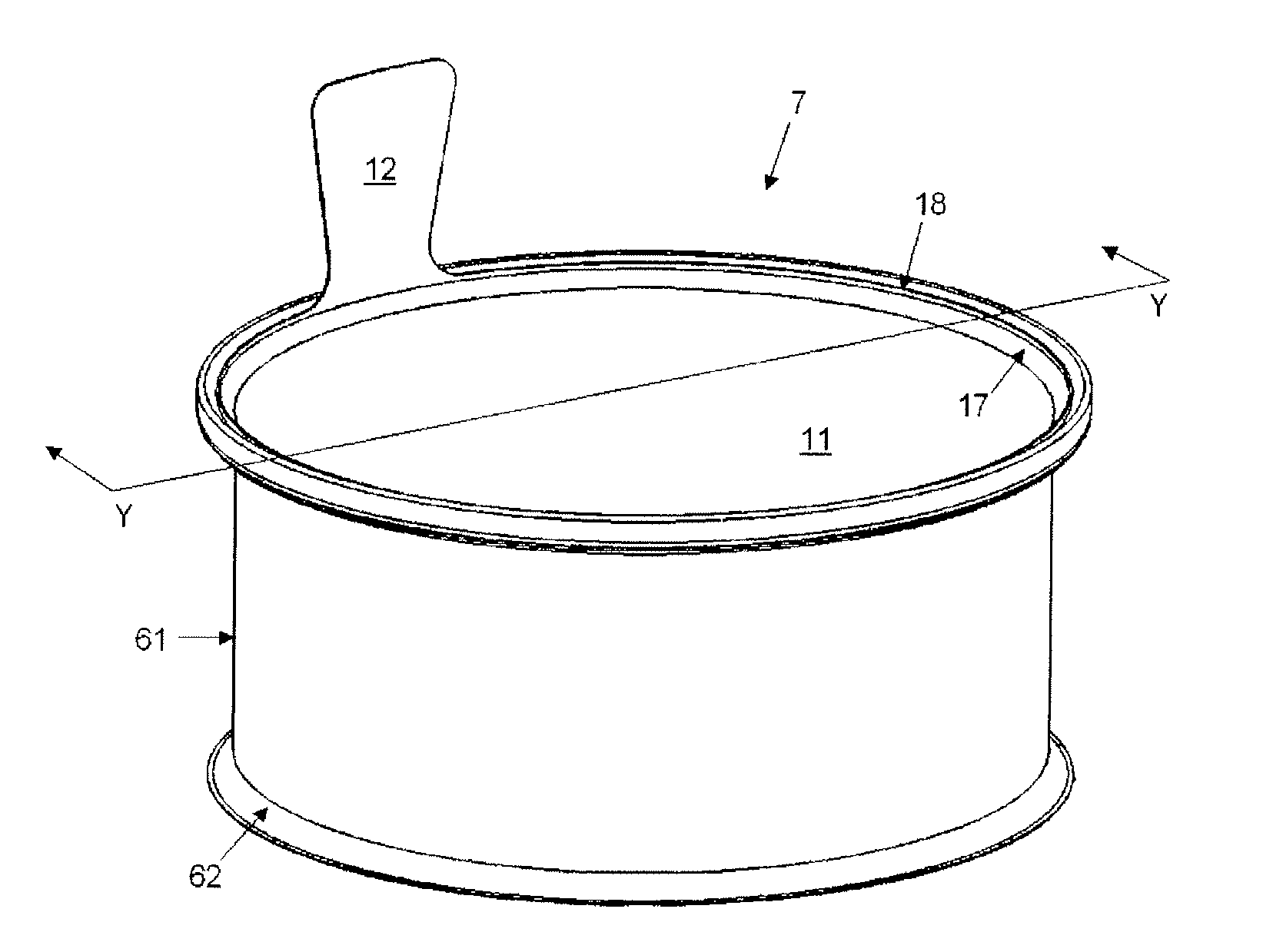
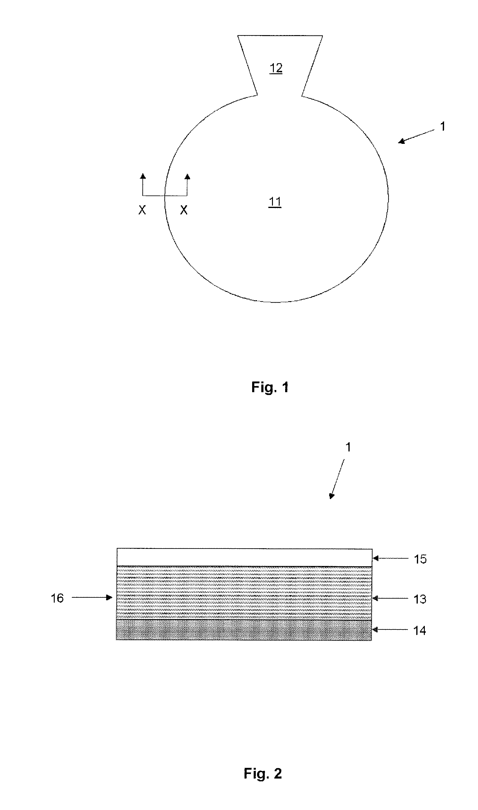
[0047]One or more lid blanks 1 are first cut (or stamped) out from a sheet (not shown) of pre-coated foil lidding material—see FIG. 1. Each blank 1 is generally circular in plan, having both a central cover portion 11 and an integral tab 12 (see FIG. 1). As shown in the cross-section view of FIG. 2, the blank 1 has a metal substrate 13 (formed in this case of aluminium) of 70 microns thickness. The lower surface of the aluminium substrate 13 includes a polypropylene-based coating 14, with the upper surface of the metal substrate including a coating of polyethylene terephthalate (PET) 15. As can clearly be seen in FIG. 2, a surface 16 of the metal substrate 13 is exposed along the peripheral cut edge of the blank 1.

[0048]One example of an apparatus and method for manufacturing the closure of the present invention is now described below:

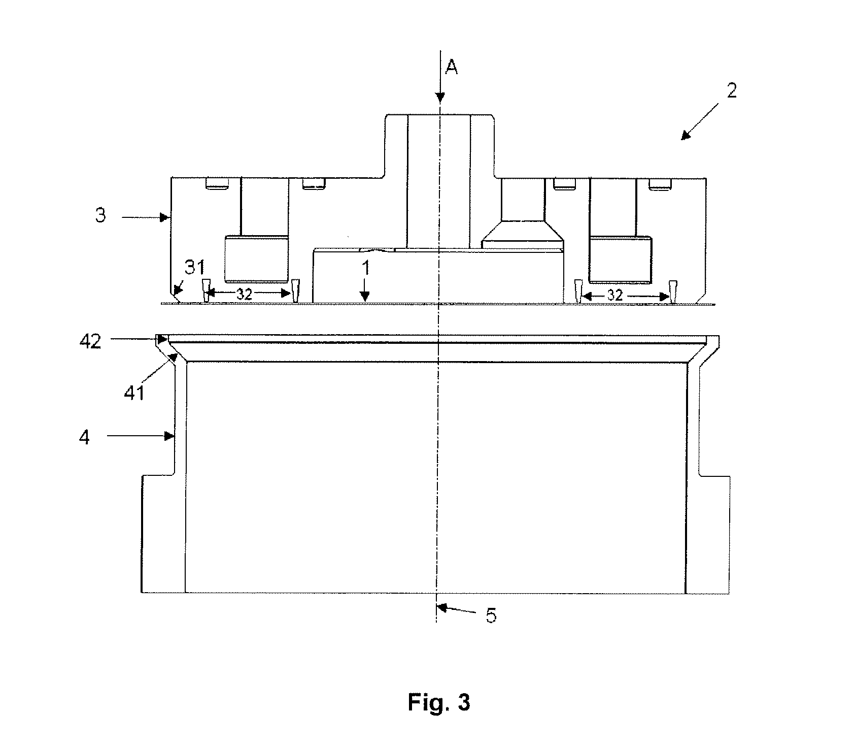
[0049]FIG. 3 shows the initial configuration of an apparatus 2. The apparatus 2 has a punch 3. The lower surface of the punch 3 is generally planar, b...


PUM


Abstract

A metal closure is described, in the form of a foil lid (1) bonded to a metal annular component (such as a container body or separate intermediate ring). The foil lid (1) and annular component are made of dissimilar metals, with the closure adapted to prevent bimetallic corrosion at the interface between the dissimilar metals of the foil lid and the annular component. The closure is adapted such that the lid comprises a peripheral wall which is upstanding from the annular component such that a gap is maintained between the annular component and an exposed metal peripheral edge of the lid. Further aspects of the invention include: i. a method for making such a metal closure; and ii. an apparatus for making such a metal closure.

Description

TECHNICAL FIELD[0001]This invention relates to a metal closure in the form of a foil lid bonded to a metal annular component (such as a container body or separate ring), the foil lid and annular component made of dissimilar metals, with the closure adapted to prevent bimetallic corrosion at the interface between the dissimilar metals of the foil lidding and the annular component. Further aspects of the invention include:[0002]a method for making such a metal closure; and[0003]an apparatus for making such a metal closure.BACKGROUND ART[0004]In the field of metal packaging for food / beverages, it is well known to seal the access opening of a container body using a foil lid. By “foil” is meant a flexible lidding material including a base layer of metal. The metal base layer provides strength to the lid, forms a barrier to mitigate loss of moisture and flavours from a filled container, and prevents contamination. The foil lid may be bonded to an intermediate metal ring, the ring then sea...

Claims


Application Information

Patent Timeline
IPC IPC(8): B65D17/34B21D51/44
CPCB21D51/46B65D17/502B65D2517/5013B65D2517/0082B65D77/2024
Inventor CAUNTER, NICHOLAS JAMESMAXWELL, IAN
Owner CROWN PACKAGING TECH
Why Eureka
Try Eureka