Device for controlled adjustment of a surgical positioning unit

a positioning unit and controlled technology, applied in the field of controlled adjustment of surgical positioning units, can solve the problems of disadvantageous overall irradiation balance for patients, low safety of patients, and low accuracy of ct based systems, so as to increase the safety of patients

Active Publication Date: 2011-09-08
BLUE ORTHO
View PDF43 Cites 62 Cited by
  • Summary
  • Abstract
  • Description
  • Claims
  • Application Information

AI Technical Summary

Benefits of technology

[0087]In another embodiment of the invention the positioning unit can be attached in a defined way at different locations on the attachment unit. Hereby the workspace can be increased in an advantageous way.
[0088]In another embodiment of the invention, the positioning unit can encompass means for angle detection. Hereby the position and/or

Problems solved by technology

Despite multiplanar X-ray control there is a relatively high rate of misplaced implants caused by the difficulty of deducing 3D information from the acquired images and by the freehand drilling.
This positive tendency is not valid for CT based systems though, for which the overall irradiation balance for the patient is disadvantageous with respect to the conventional approach because of the navigation data set that needs to be acquired additionally to the diagnosis CT data set[3].
Additionally there are supplemental costs for the CT data such that a CT based planning is only justifiable in the case where the structures to be treated show large deformations.
These systems (e.g. Siemens Arcadis Orbic) allow the navigation within multiplanar reconstructions but with reduced quality and especially with a reduced scan volume (approximatively 12 cm×12 cm×12 cm) with respect to pre operative CT data sets.
In more detail these issues are:Operating Room time compared to the conventional approachThe invasiveness necessary for the intervention (size/type of incision, attachment of reference basis to the bone, etc.)Problems with the clinical and surgical workflow being modified in a different wayPurchase cost and additional cost per intervention
An important limiting factor of navigation based systems is the necessary tracking system (mostly optical tracking) by which the registration (alignment of the planning data with the patient anatomy) as well as the positioning and alignment of the implantation instruments is performed.
On the one hand the intra operative flexibility is greatly reduced by the “line of sight” problem and the limited work space, on the other hand the achievable accuracy is limited for example because of markers being soiled by blood or the temperature sensibility of the sensor system.
Furthermore there

Method used


Image

  • Device for controlled adjustment of a surgical positioning unit
  • Device for controlled adjustment of a surgical positioning unit
  • Device for controlled adjustment of a surgical positioning unit

Examples


example 1

Spine Surgery with Medical Imaging

[0188]According to a first advantageous embodiment of the invention, illustrated on FIGS. 9-12, the adjustment device can be utilized in spine surgery performed with medical imaging.

[0189]FIG. 9 shows a detail of a spine 3 with several vertebral bones.

[0190]An attachment unit 11′, which can be seen on side and upper views, is an percutaneous support having a general H shape for supporting a positioning unit for a drill guide (not shown here).

[0191]The pins 31 are used for attachment of the attachment unit 11′ to the spine 3.

[0192]Thanks to the flanges 32, different positions for the attachment of the positioning unit and / or the referencing unit (not shown here) are possible.

[0193]At the same time the flanges 32 can be used as X-ray visible markers.

[0194]Optionally, four screws 33 are used as an additional stabilization for support on the skin, whereas the screws 33 can be likewise designed as markers.

[0195]FIG. 10 depicts an attachment unit 11′ in d...

example 2

Hip Resurfacing Surgery with Medical Imaging

[0217]A second advantageous embodiment of the invention, illustrated on FIGS. 14-17, the adjustment device can be utilized in hip surgery performed with medical imaging.

[0218]For the use of the surgical instrument the positioning unit must be attached to the object being operated (here, the femoral head).

[0219]As one can see from FIGS. 14 and 15, this is achieved by a clamp mechanism which is implemented by the attachment unit 11′. The attachment unit 11′ is flange mounted to the femoral head 3 of the bone, such that there is an essentially rigid connection.

[0220]As one can deduce from the x-ray image in FIG. 14, the referencing unit 34 is flange mounted to the attachment unit 11′. The referencing unit 34 comprises additionally x-ray visible markers 32, whereby two x-ray images (e.g. lateral view and frontal view) allow determining the coordinates in space.

[0221]There are further functions that can be implemented via the markers 32 in part...

example 3

Knee Surgery with a Navigation System

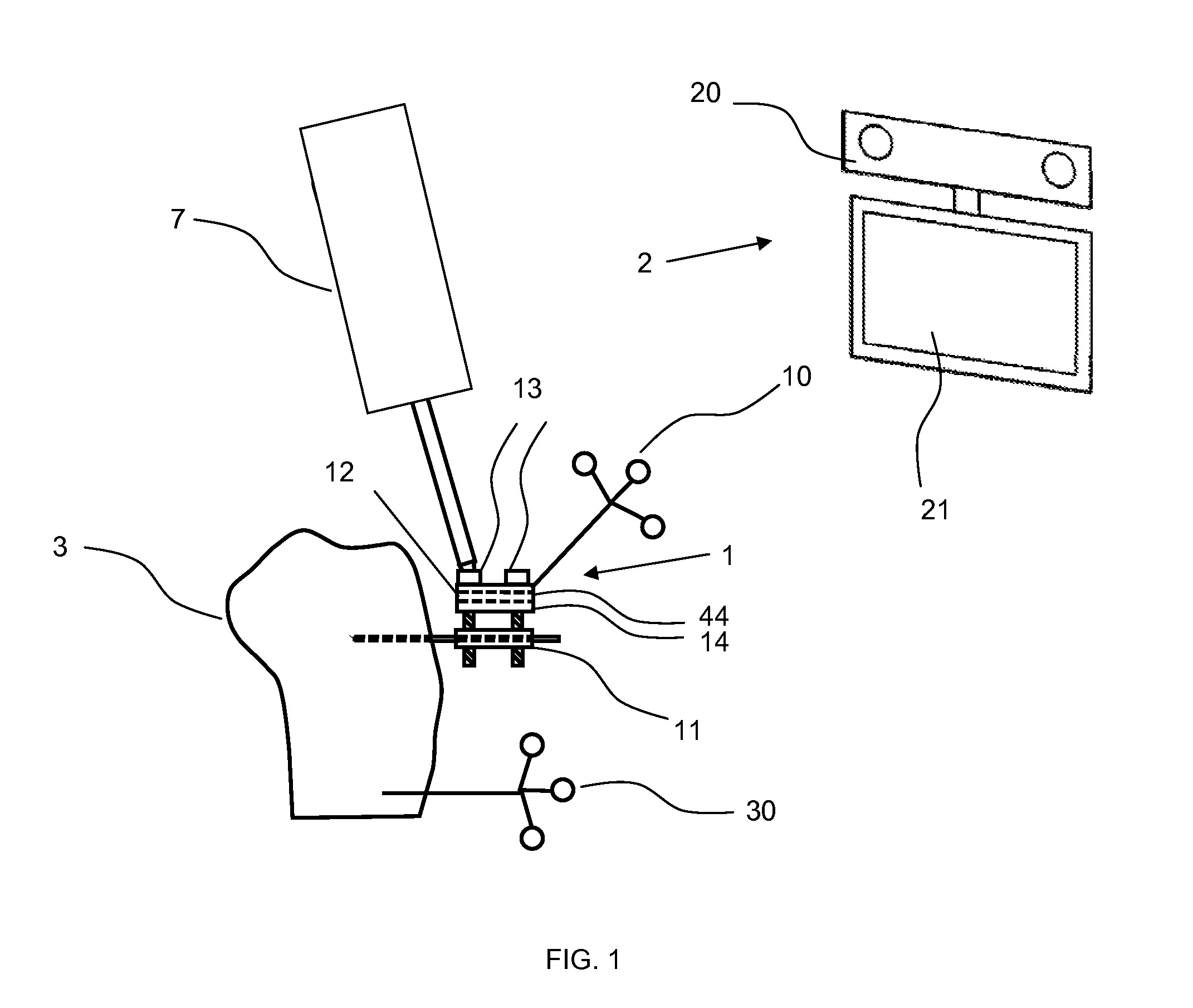
[0234]In another preferred embodiment, illustrated on FIGS. 7 and 8, the surgical application is the total replacement of the knee joint; the solid 3 is the patient's tibia or the basis of the instrument fixed to the tibia, and the tracker 30, rigidly fixed to the bone, allows the navigation system 2 to track the tibia; the instrument 1 is a cutting block on which a cutting plane 14 must be aligned with the desired target plane selected by the surgeon; the instrument mobile part position is adjustable by three screws; the position of the three screws determine a unique position of the cutting block with respect to the fixed part 11.

[0235]The cutting plane position is defined by a slope angle, a varus / valgus angle, and a cut thickness with respect to the tibia.

[0236]The target position is entered into the navigation system by the surgeon or set to default values with respect to anatomical landmarks digitized by the surgeon with the navigation syst...


PUM


Abstract

The invention concerns a device for adjusting the position of a screw (13) that is able to move a part of a surgical instrument, said device (4) comprising: —a stem (41) comprising a tip (42) suited to the head (130) of the screw (13), —an actuated system (45) for driving said stem (41) in rotation, —communication means to communicate with a control unit (21), such that the control unit (21) transmits to the actuated system (45) the number of turns to apply to the stem (41) to reach the target position of the screw (13). The invention also concerns a surgical system for alignment of surgical guide means (14, 15), comprising: —a positioning unit comprising a fixed part (11) and a mobile part (12) supporting the surgical guide means (14, 15), the position of said mobile part (12) being adjustable with respect to the fixed part (11) by screws (13), —a referencing unit for detecting the position of the positioning unit with respect to a target position of the surgical guide means, —a control unit (21) for computing the target position of screws (13), —said device (4) for adjusting the positions of the screws (13).

Description

FIELD OF THE INVENTION[0001]The invention concerns an adjustment device for adjusting the position of a screw that is able to move a part of a surgical instrument, a surgical positioning unit supporting surgical guide means, such as drill guides and cutting planes, and a method for the adjustment of surgical guide means.BACKGROUND OF THE INVENTION[0002]During transpedicular instrumentation of vertebral column segments, the insertion of surgical implant close to sensible structures requires a very high degree of precision. For protection of nerves in proximity and blood vessels a high number of control X-ray images is acquired causing an increased irradiation. Despite multiplanar X-ray control there is a relatively high rate of misplaced implants caused by the difficulty of deducing 3D information from the acquired images and by the freehand drilling. According to a meta analysis by Kosmospoulos and Schizas[1] taking into account 130 ex- and in-vivo studies regarding accuracy of pedi...

Claims


Application Information

Patent Timeline
IPC IPC(8): A61B17/56
CPCA61B17/155A61B17/157A61B17/175A61B17/7076A61B17/8615A61B17/1757A61B19/5244A61B2017/00482A61B2019/448A61B2019/4857A61B17/8875A61B34/20A61B90/98A61B2090/0811
Inventor DE LA FUENTE KLEIN, MATIASBELEI, PETERRADERMACHER, KLAUSBOYER, ANTHONYLAVALLEE, STEPHANE
Owner BLUE ORTHO
Why Eureka
Try Eureka