Laser machining apparatus and method for the manufacture of a rotationally symmetrical tool

a technology of rotational symmetry and laser machining, which is applied in the direction of manufacturing tools, metal working apparatus, laser beam welding apparatus, etc., can solve the problems of large force effect on the blank, undesired deformation, and limited technical and economic respect of grinding of very hard materials, so as to avoid quantitative negative impacts on the contour being manufactured and increase the depth of the chip groove

Active Publication Date: 2011-09-15
FRITZ STUDER AG
View PDF10 Cites 29 Cited by
  • Summary
  • Abstract
  • Description
  • Claims
  • Application Information

AI Technical Summary

Benefits of technology

[0023]The size of the pulse area can vary during the establishment of the chip groove. The pulse area may become, for example, smaller with increasing depth of the chip groove. In this way, different geometries of the chip groove can be formed in a simple manner. The pulse area can be reduced down to a pulse line or a single impact location.
[0024]The redirecting arrangement directs the laser beam impulses preferably toward impulse locations which are arranged along a predetermined pulse path. The pulse path depends on the shape of the pulse area and preferably has a meander-shaped or spiral course. Herein the pulse path may include an impact location as starting point and an impact location as end point wherein the end point is arranged at the edge of the pulse area which is assigned to the contour to be formed. The path section including the end point extends preferably parallel or tangential to relative movement direction. During the reset movement from the end point to the starting point a relatively large adjustment distance is passed which distance is substantially larger than the other adjustment paths between two subsequent impact locations along the pulse path. Since the accuracy of the positioning of the laser impulses is limited by the redirecting arrangement and the redirecting arrangement tends to overshoot, the direction of movement of the reset movement is directed away from the edge to be formed and / or the area. In this way, quantitative negative impacts on the contour being manufactured are avoided.

Problems solved by technology

The grinding of very hard materials, such as polycrystalline diamonds (PKD) of CVD diamonds (Chemical Vapor Deposition) is limited in technical as well as economical respect.
In addition, the force effects on the blank are very large and may lead to undesired deformation.
The manufacture of high-quality tools however is problematic.
However, the achievable accuracy does not comply with today's requirements.
In addition, the surfaces and edges formed in the process deviate from a straight course and have an uneven jagged course.
Although a higher accuracy and a higher quality of the surfaces and edges formed on the blank can be obtained in this way, the ablation rates which can be achieved thereby are low.
This is because the dynamics and the speed of the machines axis are limited.
For increasing the dynamics of the machine axes, large efforts and expenses are necessary which make the laser machining apparatus very expensive.
As already noted, the ablation rate in this procedure is low and machining time is correspondingly large.
Known machine axes could not possibly provide therefor.

Method used


Image

  • Laser machining apparatus and method for the manufacture of a rotationally symmetrical tool
  • Laser machining apparatus and method for the manufacture of a rotationally symmetrical tool
  • Laser machining apparatus and method for the manufacture of a rotationally symmetrical tool

Examples


Embodiment Construction

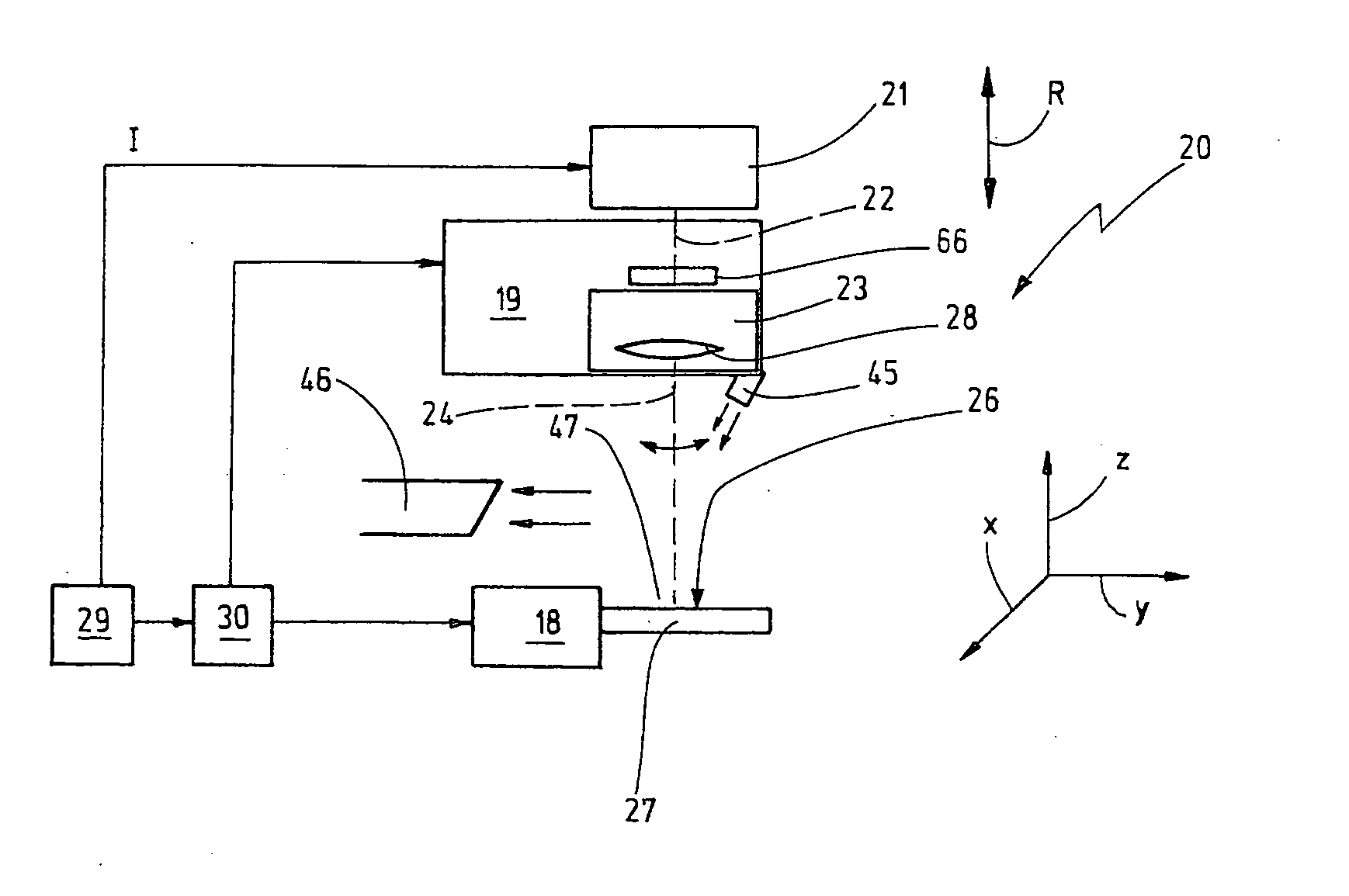
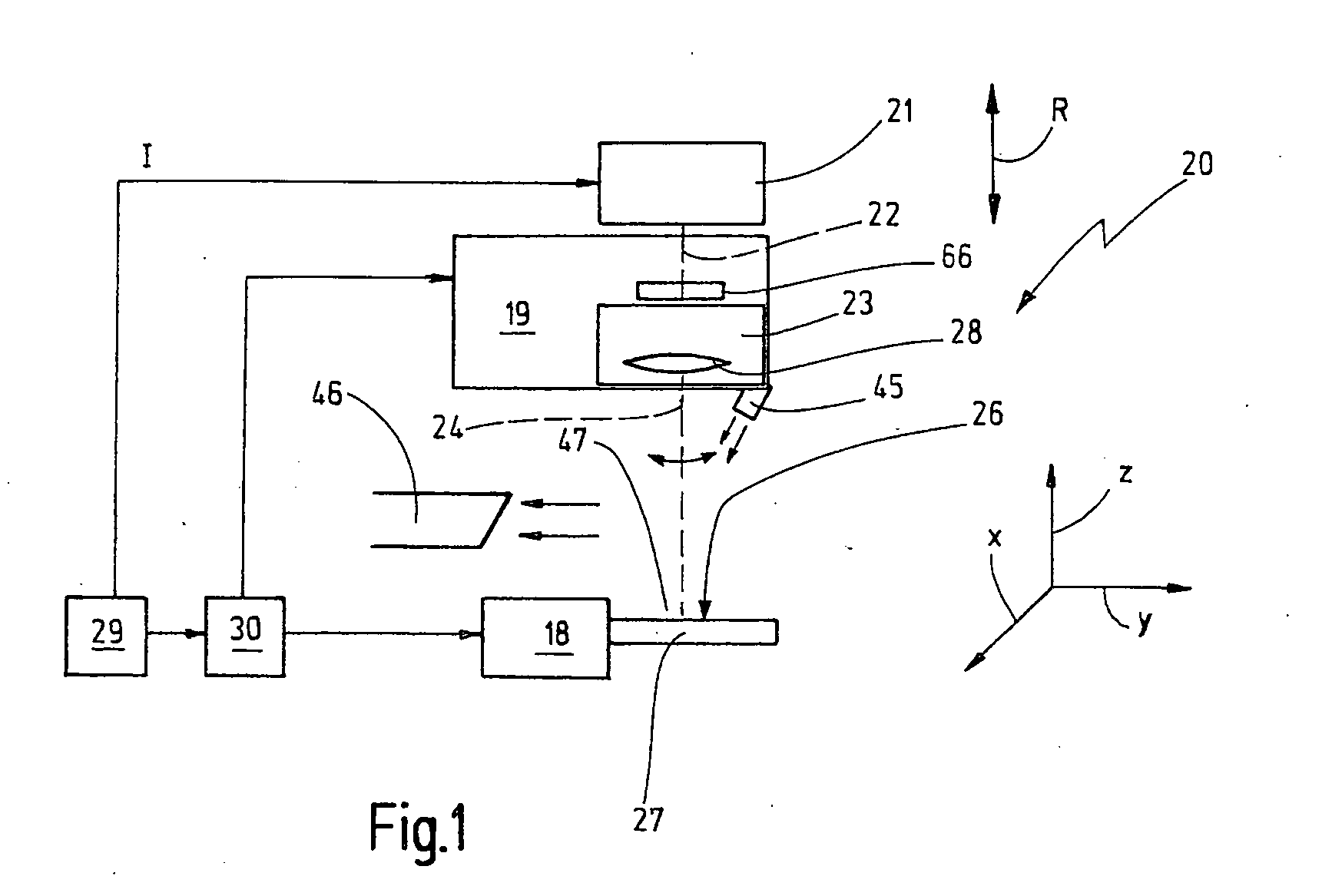
[0048]FIG. 1 shows schematically a laser machining apparatus 20. The laser machining apparatus includes a pulsed laser 21 which generates a pulsed laser beam 22 and supplies it to a laser head 19 including a redirecting arrangement 23. The redirecting arrangement 23 is capable of changing the direction of the laser beam impulses provided, and as a result, directing the laser beam impulse 24 onto a predetermined impact location 25 on the surface 26 of a blank 27. The redirecting arrangement 23 may also be called a scanner arrangement. It also comprises a focusing lens system 28. The blank 27 is supported on a tool support 18 in an accommodation area 47.

[0049]The laser machining arrangement 20 further includes a control unit 29 which controls a positioning arrangement 30 via which a relative position between the laser head 19 and the blank 27 can be adjusted and changed. The number of linear axes and rotational axes of the positioning arrangement 30 may vary.

[0050]An exemplary embodim...


PUM

PropertyMeasurementUnit
diameteraaaaaaaaaa
diameteraaaaaaaaaa
diameteraaaaaaaaaa

Abstract

The invention resides in a method and an apparatus for the manufacture of a tool from a blank (27) wherein the tool is, in particular, a rotational tool which rotates about a longitudinal axis (L). The rotational tool includes at least one cutting edge (60) and a chip groove (61). Preferably, the rotational tool is in its operating area (63) in a cross-section thereof radially symmetrical with respect to the longitudinal axis (L) thereof. It is manufactured from a cylindrical blank (27) exclusively by laser ablation using a laser machining apparatus (20) by means of a laser scanner with a pulse area (55) of, for example, rectangular contour. The laser beam impulses (24) are directed within the pulse area (55) onto a plurality of impact locations (25) disposed along a predetermined pulse path (B). This pulse area (55) is moved, like a tool, along the surface (26) of the blank (27). Hereby the chip groove (61) and subsequently the cutting edge (60) are formed from the blank (27) by sublimation of the material. The relative movement between a tool holder (18) supporting the blank (27) and the laser head (19) delivering the laser beam impulses (24) is achieved by a positioning arrangement (30) having several axes.

Description

CROSS-REFERENCE TO RELATED APPLICATION[0001]This application claims the priority of German Application No. 10 2010 011 508.8-34 filed Mar. 15, 2010.BACKGROUND OF THE INVENTION[0002]The invention resides in a laser machining apparatus and a method for the manufacture of a tool, especially a rotationally symmetrical tool from a blank. The blank is to be provided with one or several chip grooves, cutting edges, cutting faces and end flanks. The blank may include also several material layers or several joined elements as for example a hard metal shaft and a diamond tool insert.[0003]For the machining of such blanks various ablation methods are known, for example grinding. The grinding of very hard materials, such as polycrystalline diamonds (PKD) of CVD diamonds (Chemical Vapor Deposition) is limited in technical as well as economical respect. Particularly with very small dimensions only certain chip groove geometrics can be manufactured by grinding. In addition, the force effects on th...

Claims


Application Information

Patent Timeline
Patent Type & Authority Applications(United States)
IPC IPC(8): B23K26/00
CPCB23K26/063B23K26/08B23K2201/002B23K26/0823B23K26/36B23K26/0807B23K26/0622B23K26/082B23K2101/002
Inventor PLUSS, CHRISTOPH
Owner FRITZ STUDER AG
Why Eureka
Try Eureka