Honeycomb catalyst body

a catalyst body and honeycomb technology, applied in the field of honeycomb catalyst bodies, can solve the problems of reducing engine output and the like, increasing the effective diameter of the honeycomb catalyst body, and increasing the pressure loss of the exhaust gas system

Active Publication Date: 2011-09-15
NGK INSULATORS LTD
View PDF3 Cites 20 Cited by
  • Summary
  • Abstract
  • Description
  • Claims
  • Application Information

AI Technical Summary

Problems solved by technology

If a plugged honeycomb structure is mounted additionally in the exhaust gas system, there are anticipated problems such as increased pressure loss in exhaust gas system, reduction in engine output and the like.
However, in the plugged honeycomb structure described in the Patent Document 1 or 2, there are cells which do not contribute to the purification of exhaust...

Method used


Image

  • Honeycomb catalyst body
  • Honeycomb catalyst body
  • Honeycomb catalyst body

Examples


example 1

First, alumina, aluminum hydroxide, kaolin, talc and silica were mixed to prepare a raw material for cordierite formation. To 100 mass parts of the raw material for cordierite formation were added 13 mass parts of a pore former, 35 mass parts of a dispersing medium, 6 mass parts of an organic binder and 0.5 mass part of a dispersing agent, followed by mixing and kneading, to prepare a puddle. Water was used as the dispersing medium; coke having an average particle diameter of 1 to 10 μm was used as the pore former; hydroxypropyl methyl cellulose was used as the organic binder; and ethylene glycol was used as the dispersing agent.

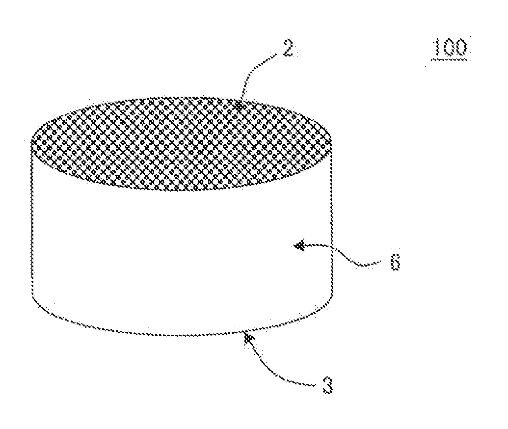
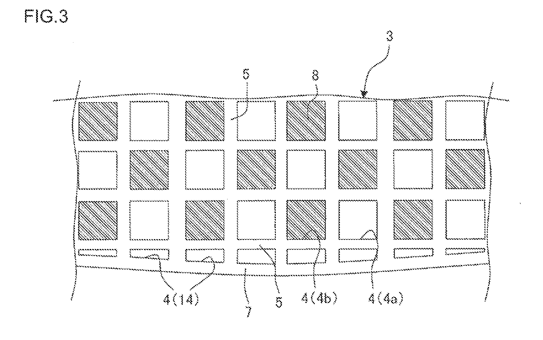
Then, the puddle was extruded using a given die to obtain a honeycomb formed body having a tetragonal cell shape and a cylindrical overall shape. The honeycomb formed body was dried using a microwave dryer and further dried completely using a hot-air dryer. The resulting honeycomb formed body was cut at the two ends for adjustment into a given size.

Then, a m...

examples 2 to 11

Comparative Examples 1 to 3

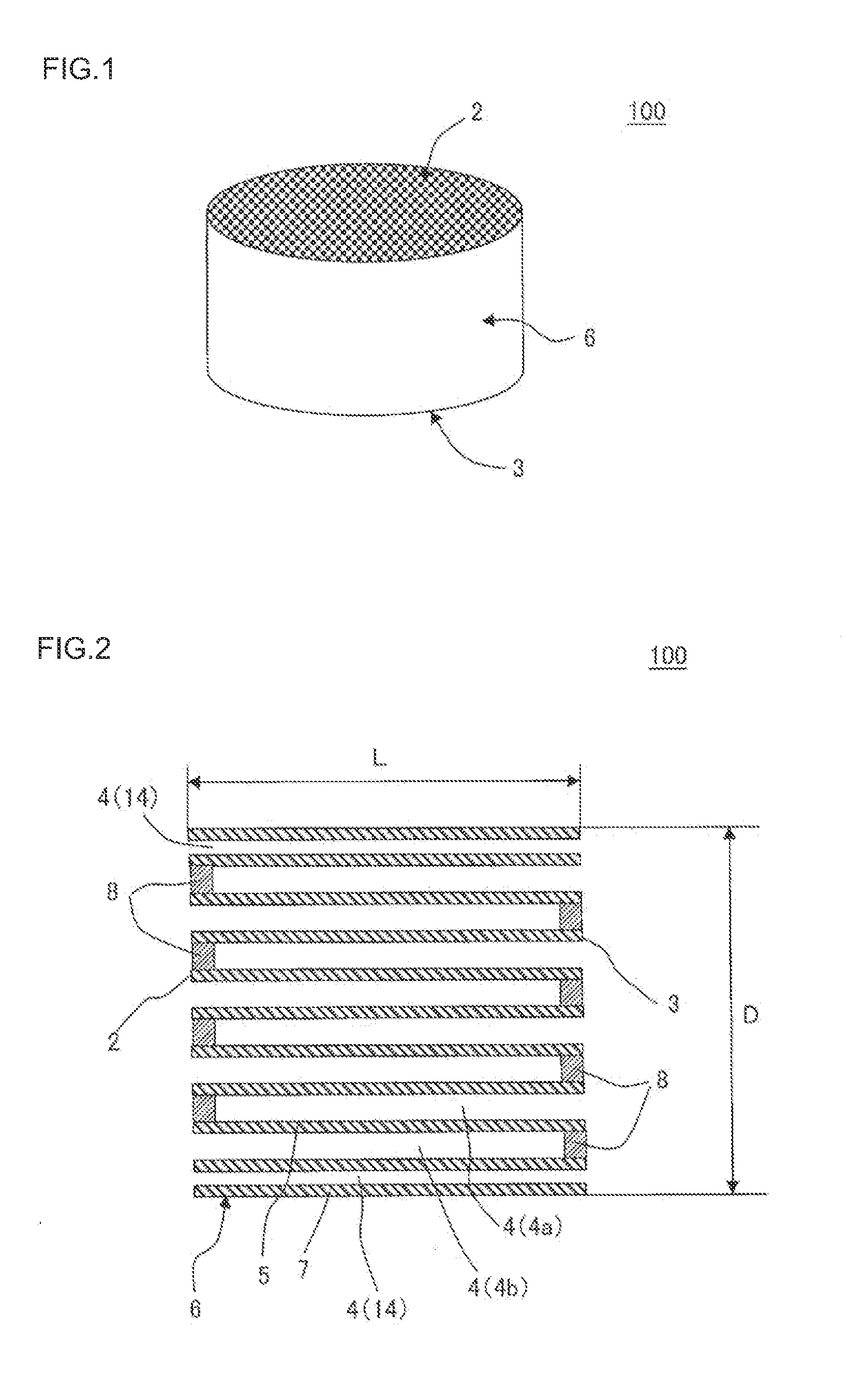
Honeycomb catalyst bodies of Examples 2 to 11 and Comparative Examples 1 to 3 were produced in the same manner as in Example 1 except that their diameters, lengths, L / D's, cell densities, rib thicknesses, porosities, cell area ratios, hydraulic diameters of complete cells, hydraulic diameters (maximums) of through-cells, areal ratios of through-cells in section, pore diameters, loaded amounts of catalyst, and amounts of noble metals were as shown in Table 1. Then, they were rated for “purification ratio”, “PM emission”, “durability”, “pressure loss” and “overall evaluation” in the same manners as in Example 1.

As is clear from Table 2, in the honeycomb catalyst bodies of Examples 1 to 11, as compared with the honeycomb catalyst bodies of Comparative Examples 1 to 3, the fine particles contained in the exhaust gas emitted from the direct injection type gasoline engine could be removed efficiently; the increases in pressure loss were small; the CO, HC and NOx...


PUM

PropertyMeasurementUnit
Fractionaaaaaaaaaa
Fractionaaaaaaaaaa
Pore sizeaaaaaaaaaa

Abstract

There is provided a honeycomb catalyst body comprising a honeycomb base body having porous partition walls forming a plurality of divided cells which extend from one end face of honeycomb base body to its other end face and which function as a fluid passage, and an outer wall present at the outermost peripheral portion of honeycomb base body, plugged portions provided so as to plug part of the plurality of divided cells, and a catalyst loaded on the partition walls of honeycomb base body. The plurality of divided cells include outermost peripheral cells formed by the partition walls and the outer wall, and of the outermost peripheral cells, those cells whose hydraulic diameter ratio to the hydraulic diameters of the cells other than the outermost peripheral cells is 5 to 75%, are through-cells having no plugged portion.

Description

TECHNICAL FIELDThe present invention relates to a honeycomb catalyst body. More particularly, the present invention relates to a honeycomb catalyst body which can efficiently remove the fine particles contained in the exhaust gas emitted from a direct injection gasoline engine, which is low in pressure loss increase, which can eliminate the CO, HC and NOx contained in the exhaust gas, and which, during the use, hardly generates cracks in the circumference.BACKGROUND ARTA reduction in fuel consumption of automobile is required from the standpoints of protection of global environment and resource saving. In the gasoline engine used mainly in passenger cars, direct injection of fuel is being pushed forward.In the gasoline engine, since fuel injection from suction port has been employed, generation of soot [particulate matter (PM)] has been slight and it has caused little problem. However, in the gasoline engine of fuel direct injection type, generation of PM is greater compared to the ...

Claims


Application Information

Patent Timeline
IPC IPC(8): B01J35/04B01J35/10
CPCB01D46/2429B01D46/2459C04B2111/0081C04B38/0009B01J37/0248B01D46/2466B01D46/247B01D46/2474B01D2046/2433B01D2046/2437B01J23/63B01J35/023B01J35/04B01J37/0036C04B35/195C04B38/0054C04B38/0074B01D46/24492B01D46/24491B01D46/2484B01D46/2482
Inventor GOTO, CHIKAYAMASHITA, MASATAKAYAMADA, TOSHIOMIYAIRI, YUKIO
Owner NGK INSULATORS LTD
Why Eureka
Try Eureka