
Intensity Noise Reduction Methods and Apparatus for Interferometric Sensing and Imaging Systems

a technology of interferometry and noise reduction, applied in the field of sensing and imaging, can solve the problems of limited operation and high cost of available auto-balancing photoreceivers, and achieve the effect of reducing noise, actively suppressing wideband (dc—250 mhz) noise, and not degrading signal quality

Active Publication Date: 2011-09-22
LIGHTLAB IMAGING
View PDF84 Cites 82 Cited by
  • Summary
  • Abstract
  • Description
  • Claims
  • Application Information

AI Technical Summary

Benefits of technology

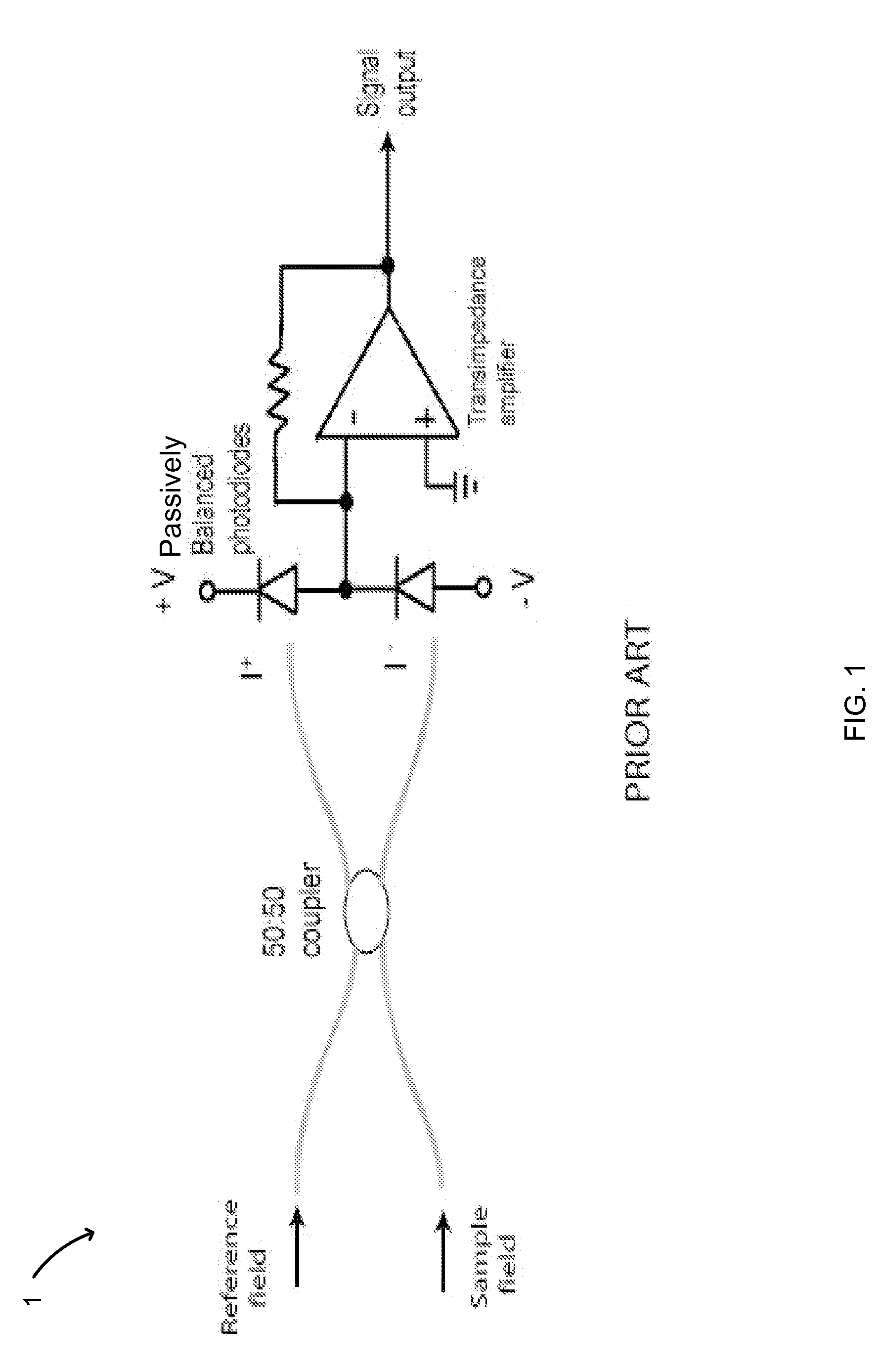
[0008]The present invention relates to electronic balancing methods, systems and apparatuses that substantially reduce noise such as intensity noise and pattern line noise in frequency-domain optical coherence tomography and in other interferometric sensing and imaging systems. One aspect of the invention is its ability to actively suppress wideband (DC—250 MHz) noise while amplifying the desired interference signals and without degrading signal quality. In this exemplary wideband noise range, DC (or direct current) corresponds to zero. In one embodiment, inclusion of zero within an auto balance method or device can help avoid saturation of the photoamplifier. This is accomplished by sampling the low-frequency intensity noise and applying active electronic feedback to cancel common-mode noise. This noise cancellation can be performed at both high and low frequencies on an automatic basis using one or more control signals. This active or automatic approach offers improvements relative to simply passively subtracting two signals as discussed above.
[0010]The methods have the additional advantage of low cost and simplicity. Currently, available auto-balancing photoreceivers are expensive and are limited to operation over a narrow low frequency band (typically <100 KHz). Techniques for extending the methods to polarization diversity detection are also described. In one embodiment, use of the methods and devices described herein result in a noise reduction of at least about 25 dB. In one embodiment, the noise reduction achieved by an embodiment of the invention ranges from about 25 dB to about 50 dB.
[0014]In one embodiment, the feedback network is configured to operate synchronously with a sweep period of the laser. The feedback network can compute the first control signal during a non-imaging cycle of the interferometer and transmits the first control signal during an imaging cycle to reduce or suppress the laser noise component. In one embodiment, the light emitted by the laser is amplitude modulated at a fixed frequency to create a first signal in a reference arm of the interferometer and wherein a second signal at an output of the system is demodulated to generate a phase-sensitive error signal that is processed by the feedback network. In one embodiment, the first attenuator is a first transistor and the second attenuator is a second transistor, wherein the first and second transistors are configured to differentially shunt photocurrents at the first input of the amplifier in response to the first and second control signals.

Problems solved by technology

Currently, available auto-balancing photoreceivers are expensive and are limited to operation over a narrow low frequency band (typically <100 KHz).

Method used


Image

  • Intensity Noise Reduction Methods and Apparatus for Interferometric Sensing and Imaging Systems
  • Intensity Noise Reduction Methods and Apparatus for Interferometric Sensing and Imaging Systems
  • Intensity Noise Reduction Methods and Apparatus for Interferometric Sensing and Imaging Systems

Examples


Embodiment Construction

[0036]The following description refers to the accompanying drawings that illustrate certain embodiments of the invention. Other embodiments are possible and modifications may be made to the embodiments without departing from the spirit and scope of the invention. Therefore, the following detailed description is not meant to limit the present invention. Rather, the scope of the present invention is defined by the appended claims.

[0037]Laser intensity noise plays an important role in frequency-domain optical coherence tomography (FD-OCT). FD-OCT can employ a rapidly tuned laser source to measure light backscattered from a sample at different optical delay times. Two-dimensional images of reflectivity versus depth at a resolution of 5-15 μm can be acquired from a scattering volume at frame rates exceeding 100 frames / s. FD-OCT has been applied widely in ophthalmology, cardiology, and other fields of medicine.

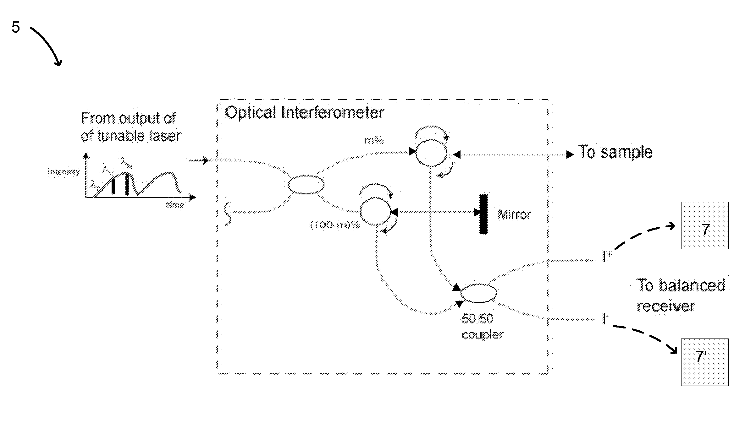
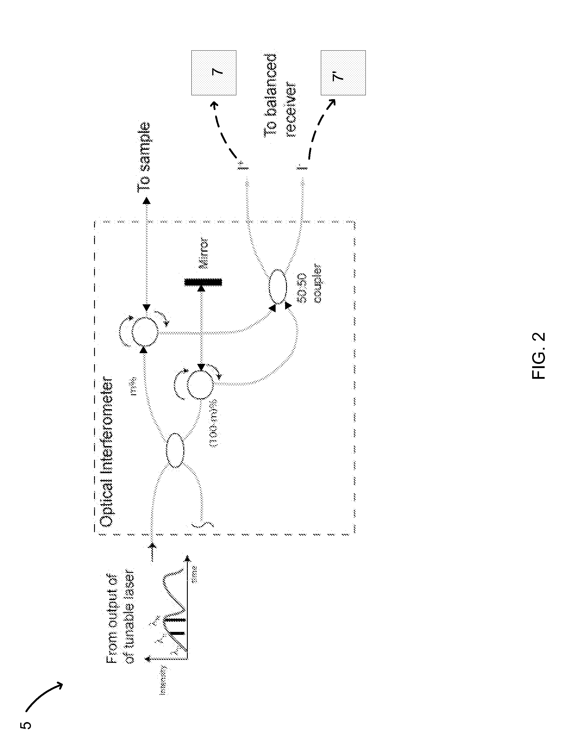
[0038]FIG. 2 shows the optical configuration of an FD-OCT system 5. Light from ...


PUM


Abstract

In part, aspects of the invention relate to methods, apparatus, and systems for intensity and / or pattern line noise reduction in a data collection system such as an optical coherence tomography system that uses an electromagnetic radiation source and interferometric principles. In one embodiment, the noise is intensity noise or line pattern noise and the source is a laser such as a swept laser. One or more attenuators responsive to one or more control signals can be used in conjunction with an analog or digital feedback network in one embodiment.

Description

RELATED APPLICATIONS[0001]This application claims priority to provisional application U.S. Ser. No. 61 / 314,759 filed Mar. 17, 2010, the disclosure of which is herein incorporated by reference in its entirety.FIELD OF INVENTION[0002]The invention relates to the field of sensing and imaging and more specifically to the design and implementation of detection systems and related components for optical coherence tomography and other data collection technologies.BACKGROUND OF INVENTION[0003]Intensity fluctuations of a light source can markedly degrade the sensitivity and dynamic range of an interferometric measurement system such as an optical coherence tomography (OCT) system. In frequency-domain data collection systems, intensity noise can be particularly troublesome. This occurs because the high-speed tunable lasers often used in such systems may exhibit rapid wavelength-dependent gain fluctuations. These fluctuations can occur while tuning over a wide spectral band. The conventional m...

Claims


Application Information

Patent Timeline
Patent Type & Authority Applications(United States)
IPC IPC(8): G01B9/02
CPCH03G3/3084H04B10/671G01B9/02083G01B9/02074G01B9/02004H04B10/616G01B9/02044G01B9/02055
Inventor SCHMITT, JOSEPH M.GRINBERG, VICTOR
Owner LIGHTLAB IMAGING
Learn More