Control device of vehicle drive-train system

a technology of control device and drivetrain, which is applied in the direction of electric control, gearing, machines/engines, etc., can solve the problems of inability to obtain sufficient engine brake, and inability to raise the input rotational speed. , to achieve the effect of absorbing or eliminating disadvantag

Active Publication Date: 2011-09-22
TOYOTA JIDOSHA KK
View PDF5 Cites 23 Cited by
  • Summary
  • Abstract
  • Description
  • Claims
  • Application Information

AI Technical Summary

Benefits of technology

According to the control device as described above, the lock-up control device engages or partially engages the lock-up clutch during the power-off downshift; therefore, a desired deceleration of the vehicle can be more quickly achieved, as compared with the case where the lock-up clutch is engaged or partially engaged after a downshift, for example. Also, shock that occurs upon engagement of the lock-up clutch can be advantageously absorbed or eliminated by shift shock that occurs during the downshift.

Problems solved by technology

In the case where the input rotational speed of the torque converter (i.e., the engine speed) becomes lower than the output rotational speed thereof upon termination of the lock-up clutch (or lock-up slip control), if the lock-up clutch is executed under a condition where there is a large difference between the input rotational speed and the output rotational speed, it may be difficult to raise the input rotational speed due to an insufficient torque capacity of the lock-up clutch, or large shock may occur due to the rise or increase of the input rotational speed, or the amount of heat generated in the lock-up clutch may exceed an allowable value.
Accordingly, if the lock-up control (or lock-up slip control) is not executed irrespective of the driver's request for engine braking, as represented by the amount of operation of the accelerator pedal being equal to or close to zero, the engine is not brought into a driven state, and a sufficient engine brake, or a sufficient deceleration, cannot be obtained.
Thus, even in the case where the driver performs a manual operation to effect a downshift in an attempt to provide a sufficient deceleration, the lock-up control is not executed since the situation where there is a large difference between the input rotational speed and output rotational speed of the torque converter does not change, as a result, a sufficient deceleration cannot be achieved.
Also, if the lock-up control is not performed, it takes time to establish a condition in which the driving wheels are driven by the engine when the vehicle is accelerated again, namely, a condition in which the input rotational speed of the torque converter becomes higher than the output rotational speed thereof, resulting in a poor response.
In this type of vehicle drive-train system, however, the engine speed that has been raised during the shift operation may be reduced at the time of completion of the shift operation; therefore, the difference between the input rotational speed and output rotational speed of the torque converter may be increased, and the lock-up control is not always performed with sufficient stability.
In this type of vehicle drive-train system, however, the operation to increase the engine speed is performed after an operation to engage the lock-up clutch is started, though the operation to engage the lock-up clutch is not necessarily executed according to the difference between the input rotational speed and output rotational speed of the torque converter; therefore, the difference between the input rotational speed and output rotational speed of the torque converter may remain large due to time lag of the engine power output or the like when the lock-up clutch is engaged, and the lock-up control is not always performed with sufficient stability.

Method used


Image

  • Control device of vehicle drive-train system
  • Control device of vehicle drive-train system
  • Control device of vehicle drive-train system

Examples


first embodiment

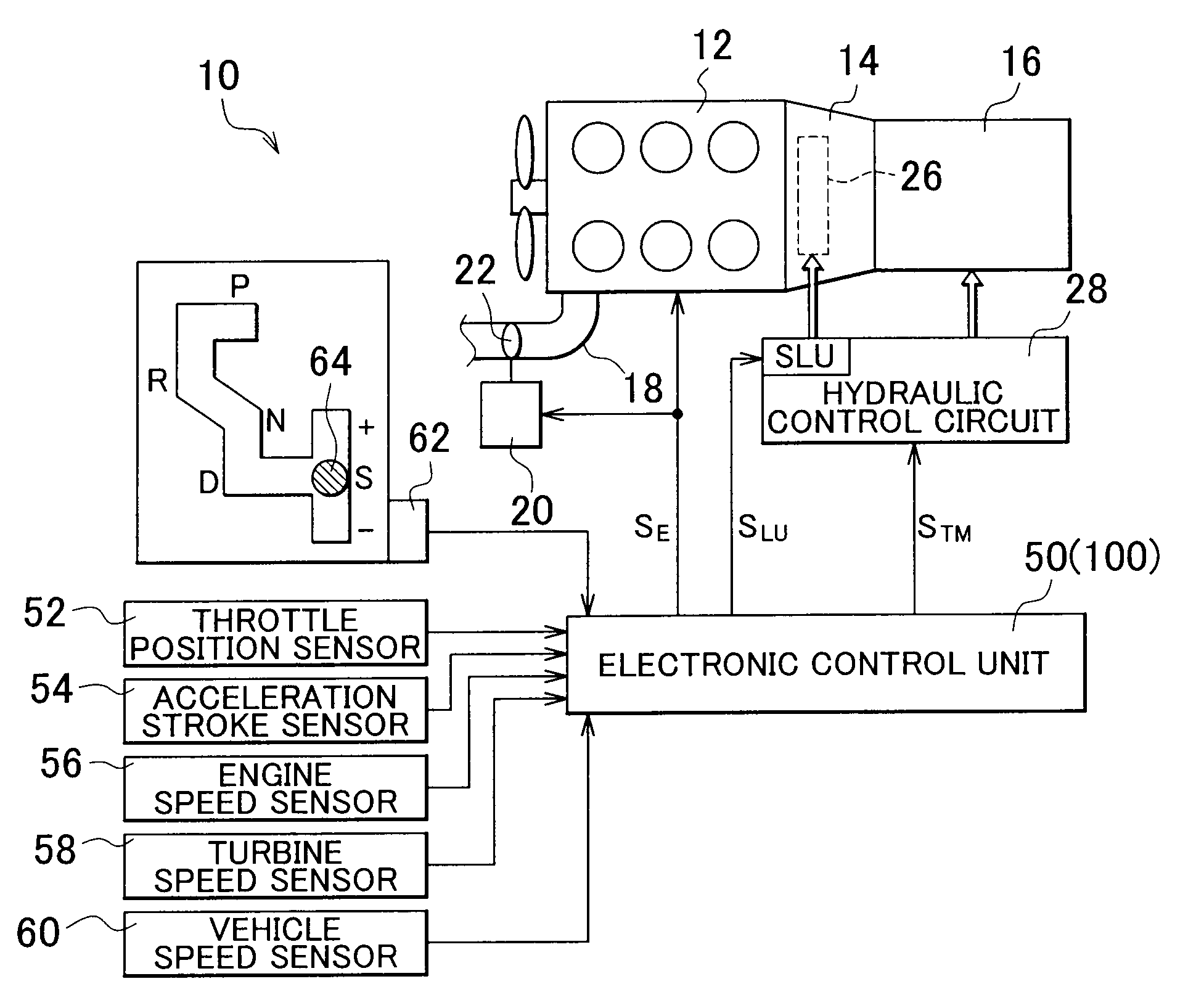
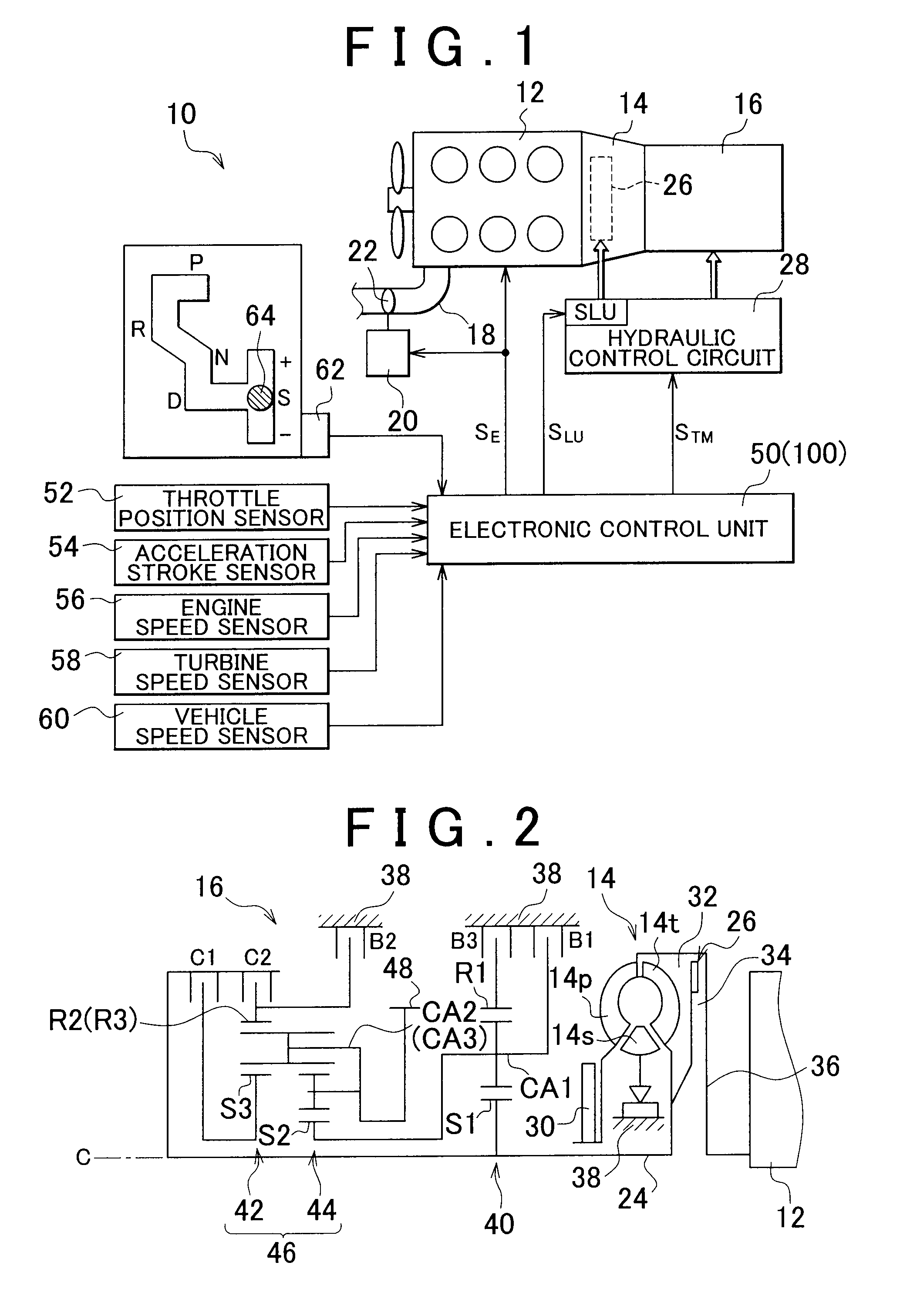
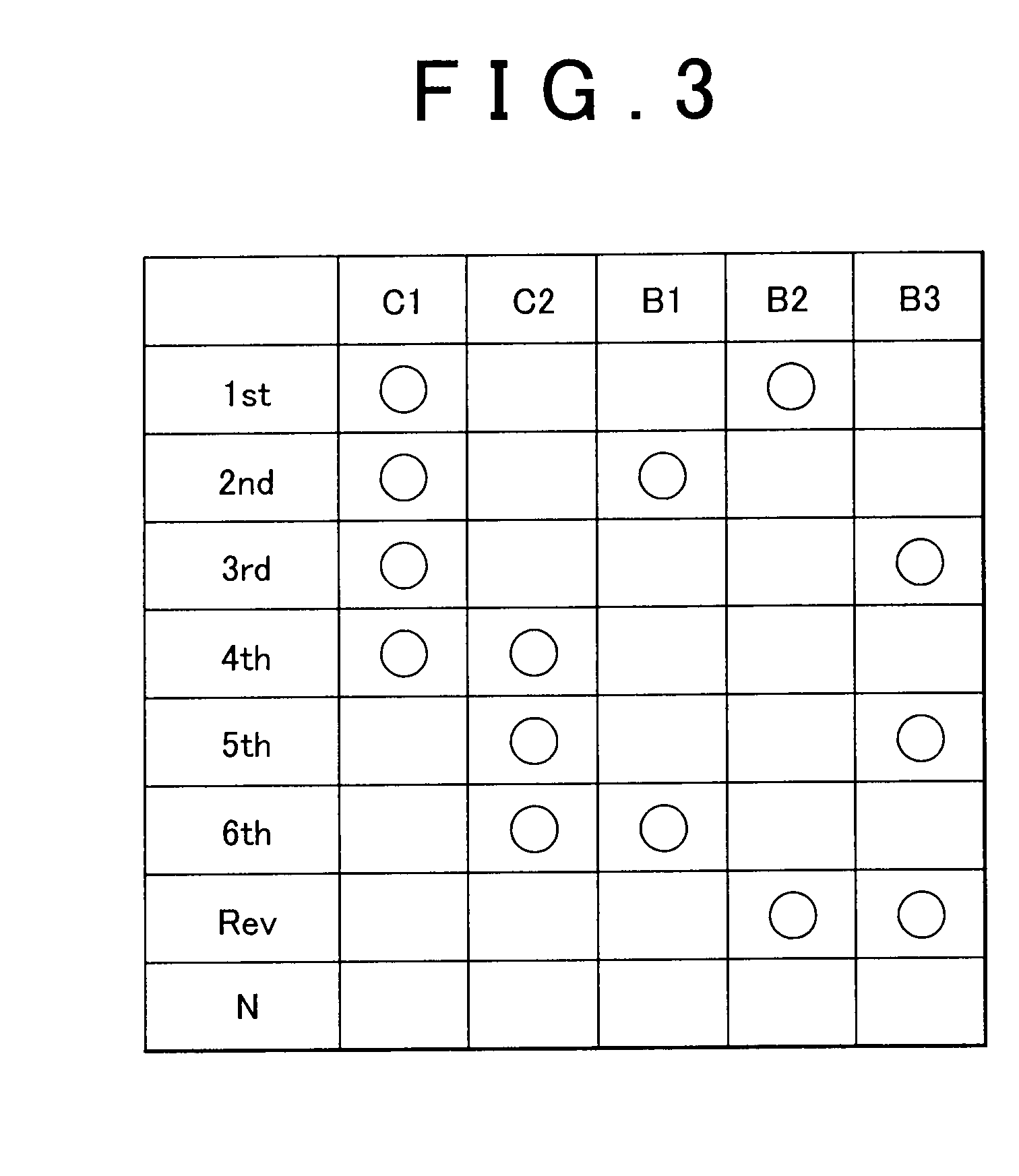
FIG. 1 illustrates a vehicle drive-train system 10 and its control system to which the invention is applied. The vehicle drive-train system 10 shown in FIG. 1 includes an engine 12 as a driving power source for running the vehicle, a torque converter 14, and an automatic transmission 16, which are arranged in series. In operation, power generated from the engine 12 is transmitted to a pair of driving wheels, via the torque converter 14, automatic transmission 16, a differential gear unit that provides another part of the drive train and the like, in this order.

The engine 12 is an internal combustion engine, such as a gasoline engine or a diesel engine, which produces driving force through combustion of fuel injected into cylinders, for example. An electronic throttle valve 22 provided in an intake pipe 18 of the engine 12 is operated, i.e., opened and closed by a throttle actuator 20 that operates based on an electric signal (electric command) from an electronic control unit 50 that...

second embodiment

Next, another embodiment (or second embodiment) of the invention will be described. In the following description of the second embodiment, the same reference numerals as used in the first embodiment will be assigned to elements or portions common to the first and second embodiments, and description of these elements or portions will not be provided.

As shown in FIG. 4, an electronic control unit 100 of the second embodiment of the invention includes a lock-up control device 102, in addition to the shift control device 68 and the blipping control device 70 included in the electronic control unit 50 of the above-described first embodiment. The lock-up control device 102 is different from the lock-up control device 72 included in the electronic control unit 50 in the following points. Namely, the lock-up control device 102 performs standby control for filling the apply-side oil chamber 32 of the hydraulic actuator of the lock-up clutch 26 with hydraulic oil of a predetermined standby pr...


PUM


Abstract

A control device of a vehicle drive-train system including an engine, an electronic throttle valve, an automatic transmission having a manual shift mode, a torque converter provided between the automatic transmission and the engine, and a lock-up clutch operable to directly connect an input member and an output member of the torque converter with each other includes a blipping control device that performs blipping control for temporarily increasing the output rotational speed of the engine by means of the electronic throttle valve, when a power-off downshift is performed while the automatic transmission is in the manual shift mode; and a lock-up control device that engages or partially engages the lock-up clutch, based on a difference between a rotational speed of the output member of the torque converter and a rotational speed of the input member thereof, which the difference is reduced after the blipping control is started.

Description

INCORPORATION BY REFERENCEThe disclosure of Japanese Patent Application No. 2010-063736 filed on Mar. 19, 2010 including the specification, drawings and abstract is incorporated herein by reference in its entirety.BACKGROUND OF THE INVENTION1. Field of the InventionThe invention relates to a control device of a vehicle drive-train system including a lock-up clutch, and is particularly concerned with control associated with engagement of the lock-up clutch.2. Description of the Related ArtA vehicle drive-train system is known which includes an engine, an electronic throttle valve operable to change the output rotational speed of the engine based on an electric command, without depending on an operation on an accelerator pedal, an automatic transmission having a manual shift mode in which shifting is effected based on a shift operation performed on a manually operated member, a torque converter provided between the automatic transmission and the engine, and a lock-up clutch operable t...

Claims


Application Information

Patent Timeline
Patent Type & Authority Applications(United States)
IPC IPC(8): B60W10/10B60W30/18B60W10/06B60W10/02B60W10/04B60W10/11F02D29/00F02D41/04F16H61/14
CPCF02D41/0205Y10T477/75F02D41/023F02D2400/12F16H59/0204F16H61/0437F16H61/143F16H2061/147F16H63/502Y10T477/735Y10T477/6333Y10T477/753Y10T477/675Y10T477/679Y10T477/78Y10T477/73Y10T477/677F02D41/022
Inventor INOUE, JUNICHIMATSUNAGA, HITOSHIHASEGAWA, YOSHIO
Owner TOYOTA JIDOSHA KK
Why Eureka
Try Eureka