Boiler Apparatus

a boiler and apparatus technology, applied in the direction of flue gas purification components, emission prevention, separation processes, etc., can solve the problems of insufficient heat, affecting and the insufficient regenerated heat of boiler apparatuses, so as to achieve efficient regenerated absorbing liquid and reduce the efficiency of steam turbines.

Active Publication Date: 2011-09-29
MITSUBISHI POWER LTD
View PDF16 Cites 17 Cited by
  • Summary
  • Abstract
  • Description
  • Claims
  • Application Information

AI Technical Summary

Benefits of technology

[0010]The present invention can efficiently regenerate absorbing liquid

Problems solved by technology

However, the above-mentioned technology does not use steam as the heat source of the regeneration tower but uses the absorbing liquid (liquid) heated by the absorbing liquid regeneration heat exchanger.
Because of this, an amount of heat is insufficient compared with the case where steam is used.
Thus, there is a possibility that the absorbing liquid may not sufficiently be regenerated by the regeneration tower.
In s

Method used


Image

  • Boiler Apparatus
  • Boiler Apparatus
  • Boiler Apparatus

Examples


first embodiment

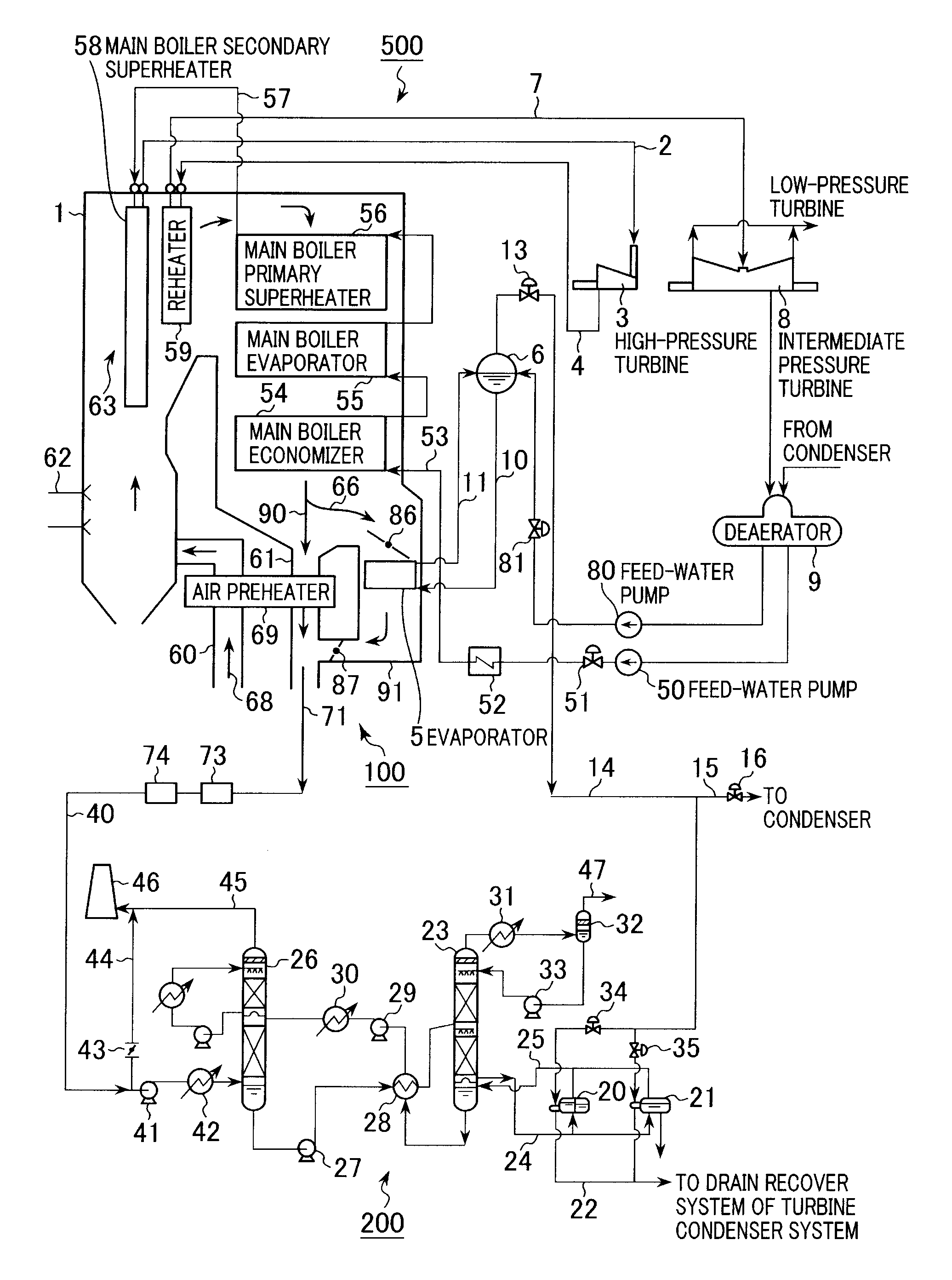
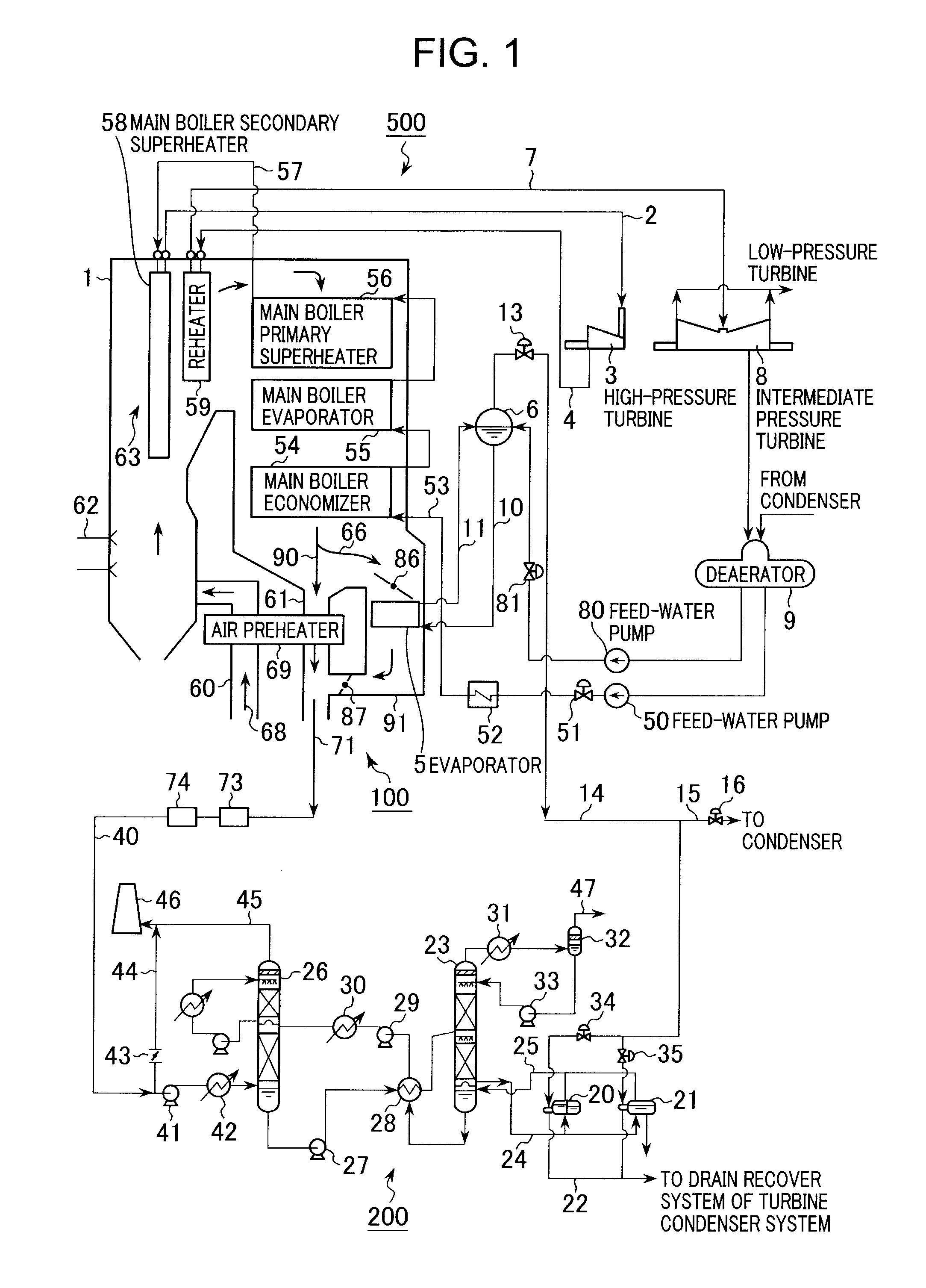
[0014]FIG. 1 is a schematic diagram of a power-generating plant according to the present invention. The power-generating plant illustrated in the figure includes a steam turbine system 500 and carbon dioxide separation-recovery equipment 200.

[0015]The steam turbine system 500 includes a deaerator 9, a boiler apparatus 100, a high-pressure turbine 3, an intermediate pressure turbine 8, a low-pressure turbine (not illustrated), and a condenser (not illustrated). The carbon dioxide separation-recovery equipment 200 includes an absorption tower 26, a regeneration tower 23 and a reboiler 20.

[0016]The deaerator 9 heats and deaerates steam condensate fed from a condenser by use of extraction steam from the intermediate pressure turbine 8. In the present embodiment, water deaerated by the deaerator 9 is fed to a main boiler economizer 54 or an evaporator drum 6 by a feed-water pump 50 or a feed-water pump 80, respectively.

[0017]The boiler apparatus 100 includes a main boiler 1, an air prehe...

second embodiment

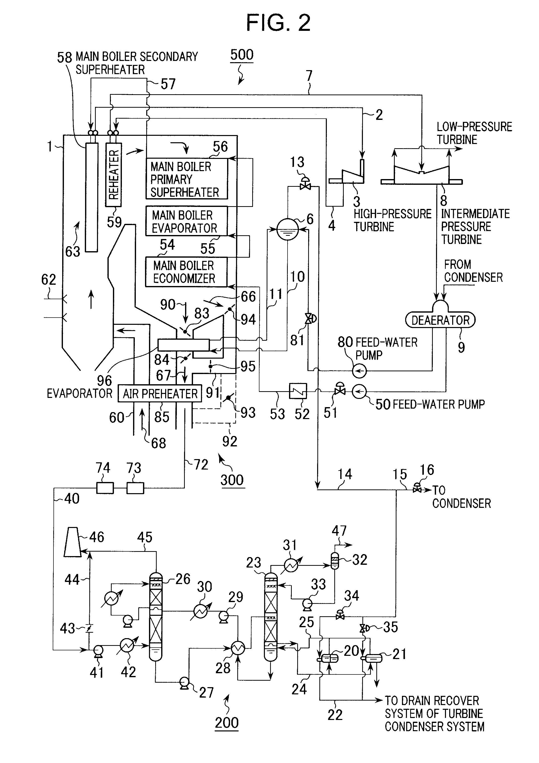
[0024]The evaporator 5 in the present embodiment is installed on a second combustion gas passage 91 installed parallel to a first combustion gas passage 61 on which the air preheater 69 is installed as illustrated in FIG. 1. The upstream side of the second combustion gas passage 91 is connected to between the main boiler economizer 54 and the air preheater 69. The downstream side of the second combustion gas passage 91 is connected to the downstream side of the air preheater 69. If the evaporator 5 is installed on the second combustion gas passage 91 installed as described above, it is possible to lead, to the evaporator 5, the combustion gas 66 having almost the same temperature as that of the combustion gas 90 led into the air preheater 69. Therefore, the design of the boiler apparatus 100 is easy compared with the case where the air preheater 69 and the evaporator 5 are arranged in series and combustion gases having the different temperatures are led into both (a second embodimen...


PUM

PropertyMeasurementUnit
Flow rateaaaaaaaaaa
Efficiencyaaaaaaaaaa

Abstract

A boiler apparatus is provided that generates a heat source capable of efficiently regenerating absorbing liquid while maintaining steam turbine efficiency to a maximum extent.
The boiler apparatus includes: an economizer 54 preheating water serving as working fluid of a steam turbine system 500; an air preheater 69 installed downstream of the economizer 54; an evaporator 5 installed downstream of the economizer 54; an evaporator drum 6 using the water vapor from the evaporator 5 to generate saturated water vapor; a reboiler 20 using the saturated water vapor from the evaporator drum 6 to evaporate the absorbing liquid from a regeneration tower 23; a steam bypass pipe 15 connected to a steam pipe 14 through which the saturated water vapor from the evaporator drum 6 passes; a steam escape valve 16 installed in the steam bypass pipe 15; an exhaust gas bypass pipe 44 connected to an exhaust gas pipe 40 connecting the air preheater 69 with an absorption tower 26; and a butterfly valve 43 installed in the exhaust gas bypass pipe 44.

Description

BACKGROUND OF THE INVENTION[0001]1. Field of the Invention[0002]The present invention relates to a boiler apparatus installed in a power-generating plant provided with equipment that separates and recovers carbon dioxide from exhaust gas.[0003]2. Description of the Related Art[0004]Equipment (carbon dioxide separation-recovery equipment) that separates and recovers carbon dioxide in exhaust gas used to generate steam is installed in a power-generating plant provided with a steam turbine in some cases. The carbon dioxide separation-recovery equipment of this type includes an absorption tower and a regeneration tower. The absorption tower brings absorbing liquid such as amine or the like and exhaust gas into contact with each other to absorb carbon dioxide. The regeneration tower heats the absorbing liquid from the absorption tower to separate carbon dioxide therefrom, thereby regenerating the absorbing liquid.[0005]There is known a method of using working fluid (steam) of a steam tur...

Claims


Application Information

Patent Timeline
IPC IPC(8): F01K23/06F22B37/00
CPCB01D53/1425B01D53/1475B01D53/343B01D2252/204B01D2258/0283Y02C10/06F22B37/008F23J15/006F23J2215/50F23J2219/40F01K13/00F22B31/08Y02C20/40Y02E20/32
Inventor MISHIMA, NOBUYOSHISUGIURA, TAKASHIKOSAKA, TETSUYA
Owner MITSUBISHI POWER LTD
Why Eureka
Try Eureka