Geothermal pipe system

Active Publication Date: 2011-09-29
G I PATENTS LLC
View PDF14 Cites 25 Cited by
  • Summary
  • Abstract
  • Description
  • Claims
  • Application Information

AI Technical Summary

Benefits of technology

[0028]One feature of the present invention is that it is preferably made from a bi-modally structured, high density polyethylene material. Presently, the Applicants' preferred material for manufacturing the device is a plastic known throughout the world (except in the U.S.) as “PE-100” and which is known in the United States as “PE4710”. The Applicants' preferred plastic has a bi-modal structure, rather than the unimodal structure that is commonly used in connection with known pipes of the prior art. This bi-modal structure results in a higher strength pipe, so that a pipe of a given diameter is capable of withstanding much higher pressures than the unimodal pipe that it replaces. Additionally, the bi-modal structure results in better “slow crack resistance” and also better “rapid crack resistance”, which results in both more rigid and is less subject to failure. Applicant believes that a bi-

Problems solved by technology

For example, although metal pipes have a greater thermal conductivity than plastics, e.g. polybutylene piping, steel and metal pipes are not preferred for use as they have a propensity to corrode, and thereby fail over a reasonably short period of time.
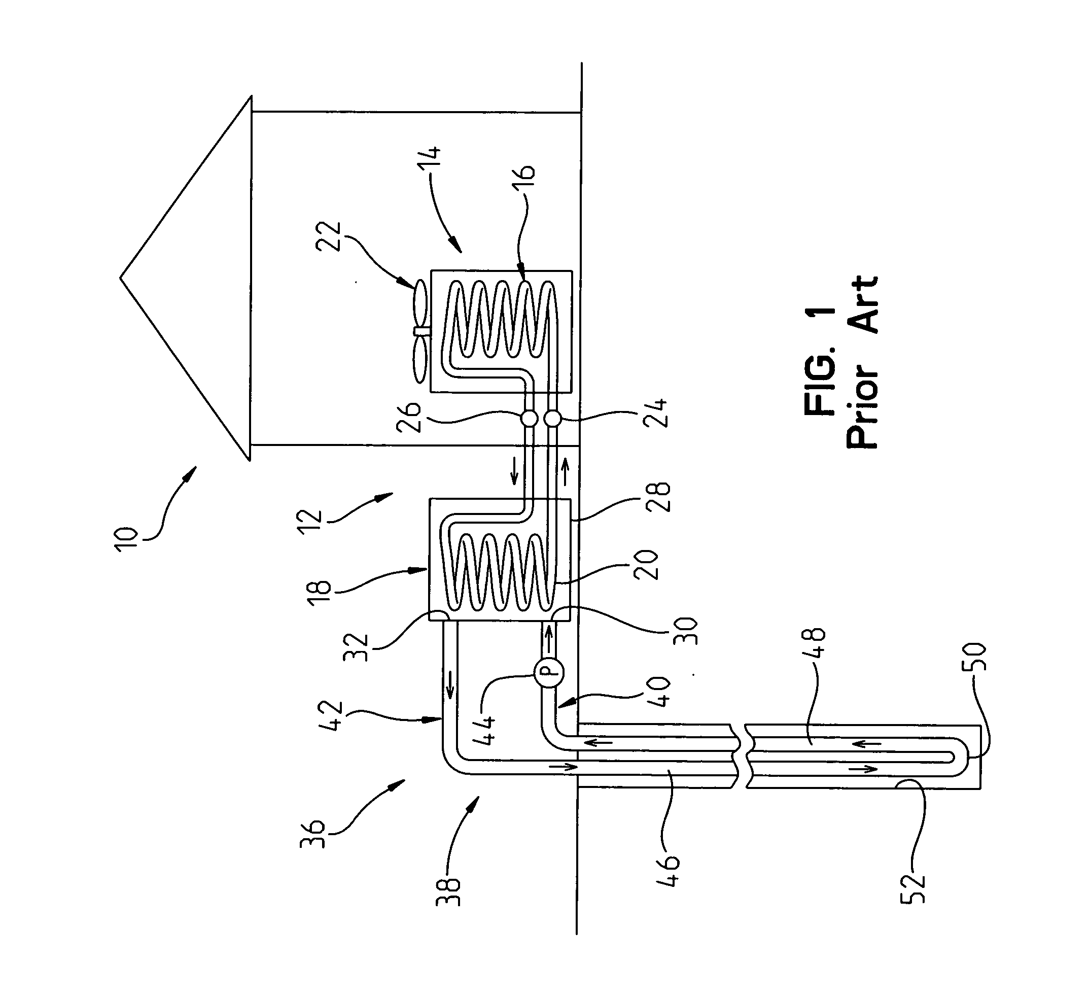
Unfortunately, the grout adversely impacts the heat transfer capabilities of the pipe that are usually overcome by drilling the bore hole much deeper than if the pipes 46, 48

Method used


Image

  • Geothermal pipe system
  • Geothermal pipe system
  • Geothermal pipe system

Examples


embodiment 400

[0086]A second alternate embodiment 400 is shown in FIGS. 22 and 23.

[0087]The device shown in FIGS. 22 and 23 comprises a modification of a bisect type geothermal pipe system. In particular, the pipe 400 comprises a three-chamber pipe having a relatively larger inflow section 404, a relatively smaller outflow section 406, a pair of dividing walls 408, 410 to divide the inflow section 404 from the outflow section 406, and a central passageway 412 through which grout can travel. Grout can travel axially down through a central pipe 412, and either out the bottom of the pipe (and the bottom of the end cap through its central aperture) or alternately, out one of the side aperture 265 that are formed in the pipe 210. The side passageways allow grout being pumped down the pipe, to flow out one of the side flow aperture 265, and into the space S that exists between the exterior of the outer wall 416 of the pipe, and the interior surface of the wall W of the bore hole.

[0088]It will be noted ...

embodiment 540

[0096]FIG. 29 shows another alternate embodiment, that is a variation of the alternate embodiment shown in FIG. 28. The embodiment 540 shown in FIG. 29 comprises a three-piece pipe, having a kidney-shaped inflow portion 542 that is generally similar to inflow portion 522 (FIG. 28) and an outflow portion 544 that is generally similar to outflow portion 524 (FIG. 28), and a third piece that comprises a generally circular cross-section, cylindrical axially extending and centrally disposed grout pipe 546.

[0097]FIG. 30 shows another alternate embodiment geothermal pipe 560. The geothermal pipe 560 includes an inflow pipe portion 562 and an outflow pipe portion 564 that are generally similarly sized, rather than differently sized, such as in FIG. 1-29 where the inflow tube has a larger volume than the outflow tube. Although the version shown in FIG. 30 would not have the relative flow rate differential advantages of the other embodiments, it would have an advantage of being less expensive...

embodiment 580

[0098]The final geothermal pipe embodiment 580 shown in FIG. 31 is generally similar to pipe 560 shown in FIG. 30, as the inflow and outflow tubes 582, 584 are both kidney-shaped and are generally have the same cross-sectional shape and size.

[0099]However, the pipe 580 shown in FIG. 31 also includes a separate, third component that comprises a grout pipe 586 that is centrally disposed and extends axially down the length of the pipe.


PUM


Abstract

A pipe is provided for use in a geothermal heat exchange system. The pipe is insertable in a bore hole having a proximal end disposed relatively closer to a surface of the earth, and a distal end disposed relatively further from the surface of the earth. The pipe comprises an inflow pipe portion having a first end and a second end, an outer wall portion and an inner wall portion extending between the first and second ends for defining an inflow chamber that extends generally between the first end and the second end of the inflow pipe portion. Water can flow through the inflow chamber between the first and second ends of the inflow pipe portion in a direction toward the distal end of the bore hole.

Description

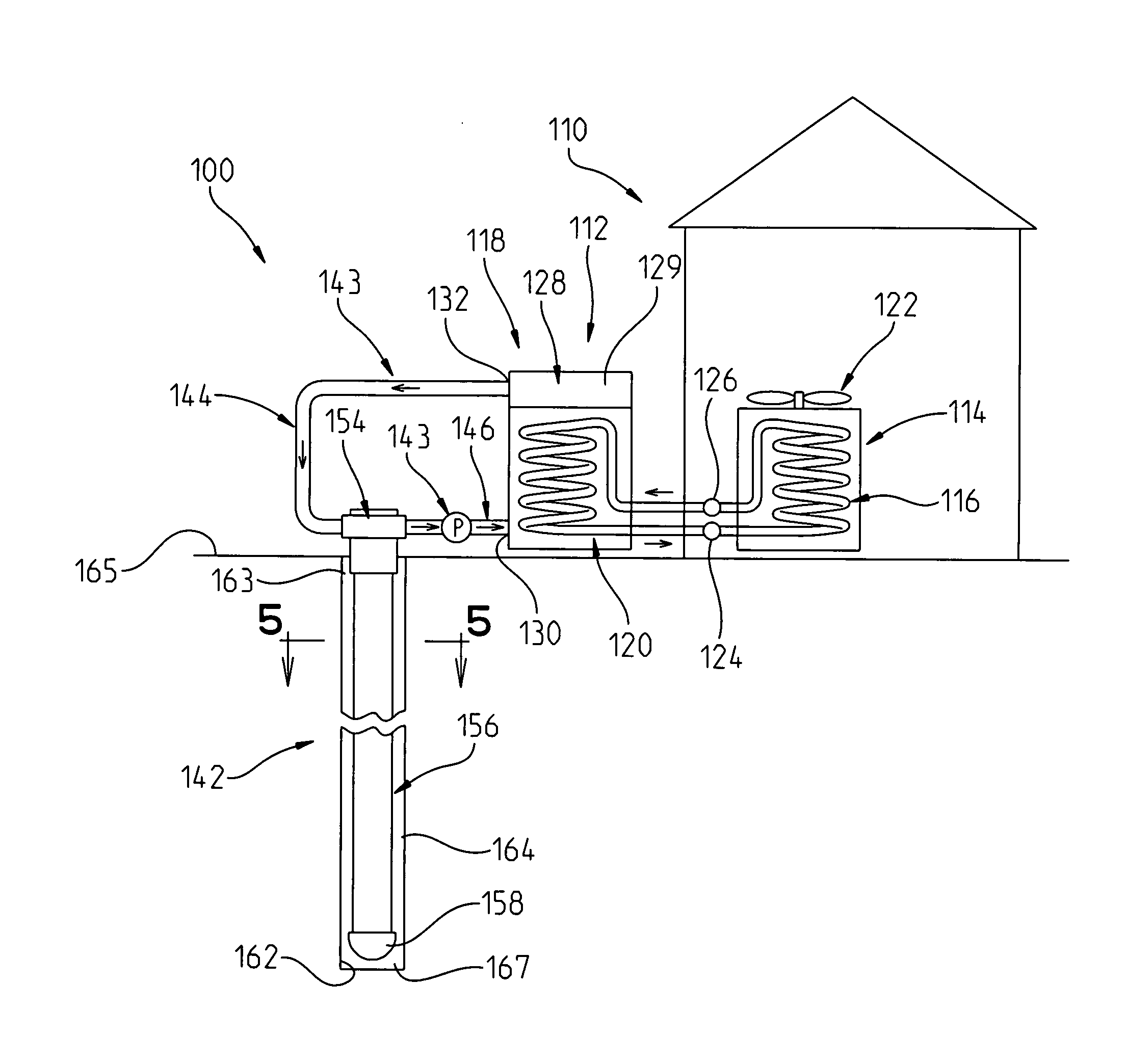
PRIORITY CLAIM[0001]The instant application claims priority to James R. Hardin, U.S. Provisional Patent Application No. 61 / 340,988 filed on 25 Mar. 2010, which is fully incorporated herein by reference.I. TECHNICAL FIELD OF THE INVENTION[0002]The present invention relates to a heat exchanger, and more particularly to a heat exchanger that is especially well adapted for use in geothermal heating and cooling systems, as a thermal energy storage device.II. BACKGROUND OF THE INVENTION[0003]A geothermal heating and cooling system obtains its ability to aid in the heating or cooling of a building by exploiting the general constancy of ground temperatures. A typical geothermal heating system comprises a closed loop pipe system through which water is pumped. A portion of the pipe is disposed underground in one or more (usually several), bore holes that are drilled into the ground. As the water in the pipe travels in the pipe down and up the bore hole(s), the temperature of the ground surrou...

Claims


Application Information

Patent Timeline
IPC IPC(8): F16L9/00
CPCF16L9/006Y02E10/125F24J3/083F16L9/19F24T10/15Y02E10/10Y02B10/40
Inventor HARDIN, JAMES
Owner G I PATENTS LLC
Why Eureka
Try Eureka