Complex Crystal Phosphor, Light Emitting Device, Surface Light Source Apparatus, Display Apparatus, and Lighting Device

a complex crystal phosphor and light-emitting device technology, applied in the field of phosphor, can solve the problems of difficult to implement sufficient overall color rendering, low half-amplitude of a conventional red phosphor, and inability to achieve the desired natural white light, etc., to achieve excellent thermal and chemical stability and high color rendering

Active Publication Date: 2011-09-29
SAMSUNG ELECTRONICS CO LTD
View PDF10 Cites 14 Cited by
  • Summary
  • Abstract
  • Description
  • Claims
  • Application Information

AI Technical Summary

Benefits of technology

[0009]An aspect of the present invention provides a complex crystal phosphor emitting red l

Problems solved by technology

In particular, in case in which a red phosphor and one or more of other phosphors are combined to be used, if a half amplitude of each of the phosphors is low, a sufficient color rendering index (or a sufficient color rendition index number) cannot be secured and there is a limitation in implementing desired natural white light.
In particular, the half amplitude o

Method used


Image

  • Complex Crystal Phosphor, Light Emitting Device, Surface Light Source Apparatus, Display Apparatus, and Lighting Device
  • Complex Crystal Phosphor, Light Emitting Device, Surface Light Source Apparatus, Display Apparatus, and Lighting Device
  • Complex Crystal Phosphor, Light Emitting Device, Surface Light Source Apparatus, Display Apparatus, and Lighting Device

Examples


embodiment 1

[0079]SiO2, Si3N4, Al2O3, Eu2O3, and SrCO3 were weighed in the following amounts to prepare raw materials, and the raw materials were mixed with an ethanol solvent by using a ball mill.

[0080]SrCO3: 1.259 g

[0081]SiO2: 1.585 g

[0082]Si3N4: 1.134 g

[0083]Al2O3: 1.345 g

[0084]Eu2O3: 0.083 g

[0085]The ethanol solvent in the raw mixture was volatilized by using a dryer, the dried raw mixture was put in a crucible, and the crucible filled with the raw mixture was inserted into a heating furnace and fired at 1,950° C. for 8 hours in a gaseous state under N2 atmosphere.

[0086]The fired phosphor was crushed and then subjected to a post-thermal treating process and a pickling process to obtain a complex crystal phosphor.

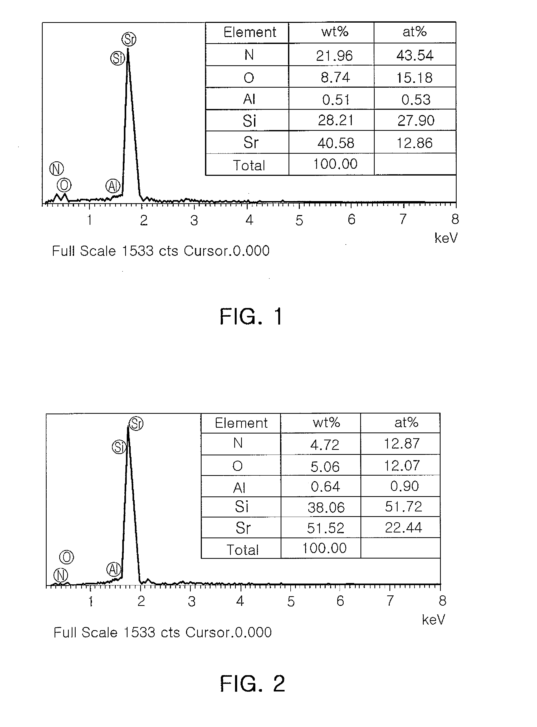
[0087]EDAX results obtained by analyzing the particle shape of the synthesized complex crystal phosphor and the components of respective phosphor particles constituting the complex crystal phosphor are shown in FIGS. 1 and 2.

[0088]With reference to FIGS. 1 and 2, the results of anal...

embodiment 2

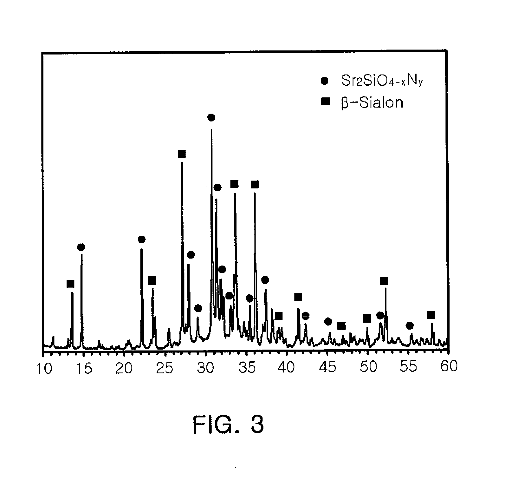
[0110]A complex crystal phosphor was prepared through a process similar to that of Embodiment 1 such that it has a first crystal corresponding to Sr2SiO4, a second crystal corresponding to the β-sialon crystal containing aluminum (Al), and an additional third crystal corresponding to Sr2Si5O8, compared with Embodiment 1.

[0111]FIG. 5 is an XRD graph of the complex crystal phosphor prepared according to Embodiment 2 of the present invention. As shown in FIG. 5, the peak corresponding to the Sr2SiO4, the peak corresponding to the β-sialon crystal containing aluminum (Al), and the peak corresponding to the additional Sr2Si5O8 crystal were observed.

[0112]The first crystal representing the Sr2SiO4 crystal peak was analyzed to be Sr2SiO2.55N1.7, the second crystal representing the aluminum (A)-contained β-sialon crystal peak was analyzed to be Si5.25Al0.75O0.75N7.25. Also, the third crystal corresponding to the Sr2Si5O8 crystal peak was analyzed to be Sr2Si5O1.3N7.14.

[0113]Thus, it was con...


PUM


Abstract

A complex crystal phosphor is an inorganic composition containing at least an M element, an Al element, silicon, oxygen, and nitrogen. The inorganic composition has particles having at least two types of crystal phase, and the at least two types of crystal phase include a first crystal phase which is the same as a M2SiO4 crystal and a second crystal phase as a β-sialon crystal. Here, M is at least one element selected from the group consisting of (Mg), calcium (Ca), strontium (Sr), and barium (Ba).

Description

CROSS-REFERENCE TO RELATED APPLICATIONS[0001]This application claims the priority of Korean Patent Application No. 2010-27313 filed on Mar. 26, 2010, in the Korean Intellectual Property Office, the disclosure of which is incorporated herein by reference.BACKGROUND OF THE INVENTION[0002]1. Field of the Invention[0003]The present invention relates to phosphor and, more particularly, to a complex crystal phosphor having high level light emission characteristics, excellent thermal and chemical stability, a light emitting device using the same, a surface light source apparatus, a display apparatus, and a lighting device.[0004]2. Description of the Related Art[0005]In general, a wavelength conversion phosphor material is used to convert a particular wavelength of light from various light sources into a desired wavelength of light. In particular, a light emitting diode (LED), among various light sources, is able to be driven with low power consumption and has excellent light efficiency so ...

Claims


Application Information

Patent Timeline
IPC IPC(8): H05B37/02H01L33/50F21V7/22
CPCC09K11/0883H01L33/502C09K11/7734C09K11/77347C09K11/77348H01L33/26C09K11/77067C09K11/77068C09K11/77927C09K11/77928
Inventor KIMRYU, JEONG HOKIM, SANG HYUNYOON, CHUL SOO
Owner SAMSUNG ELECTRONICS CO LTD
Why Eureka
Try Eureka