Method and apparatus for a subterranean and marine-submersible electrical transmission system for oil and gas wells

a submerged electrical transmission system and submerged technology, applied in the direction of insulated conductors, cables, instruments, etc., can solve the problems of limiting the weight of submerged electrical cables, the inability to repair or replace optical fiber, and the inability to use current wire line logging cables in the oil and gas industry

Inactive Publication Date: 2011-09-29
SMITH DAVID RANDOLPH
View PDF5 Cites 37 Cited by
  • Summary
  • Abstract
  • Description
  • Claims
  • Application Information

AI Technical Summary

Benefits of technology

[0016]The present invention is directed to methods and apparatus to construct electrically powered submersible transmission systems comprising novel combinations of geometry, methods and apparatus of construction, new materials of construction, and new functionality for well logging systems. This serves the industrial purpose of creating more durable, repairable, safer, smaller, submersible electrical transmission lines for the oil and gas and as marine industry.

Problems solved by technology

However, the current logging cables used in the oil and gas industry are not ideally suited to the deployment of optical fiber.
Moreover, when an optical fiber deployed in current logging cable breaks or darkens, the current wire line logging cables are not easily amenable to repair or replacement of the optical fiber.
As water depths from which hydrocarbons are extracted continue to get deeper, sometimes over 10,000 feet of water depth, the weight of submersible electrical cables becomes a limiting factor.
There are fundamental design problems with current industry teaching towards 
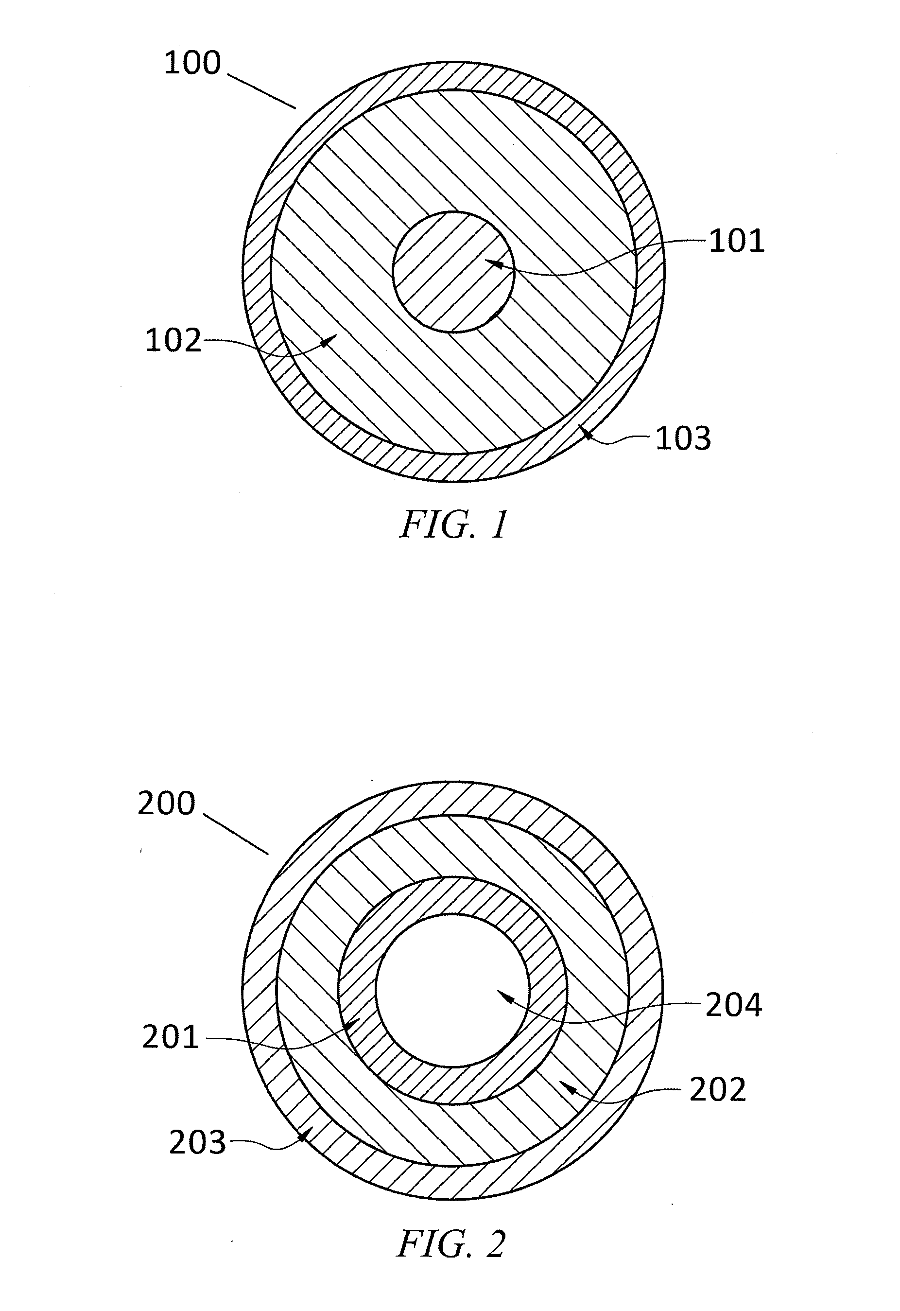
electric wire line logging cable.
One such problem is related to the steel wires used as structural members and the combination of these wires and subsequent bundle or wire wrap geometry with the electrical wires and optical fibers disposed in said current well logging cable systems.
Firstly, the initial capital cost of the steel wires used as structural members in the logging wire line of the current state of the art reduces the number of wells that can afford the logging technology.
These cables are expensive and difficult to repair.
The weight of the additional steel for strength and impact protection of the electrical conductor cable requires expensive surface deployment and retrieval systems sufficient to deploy and extract the heavy electric wire line cables.
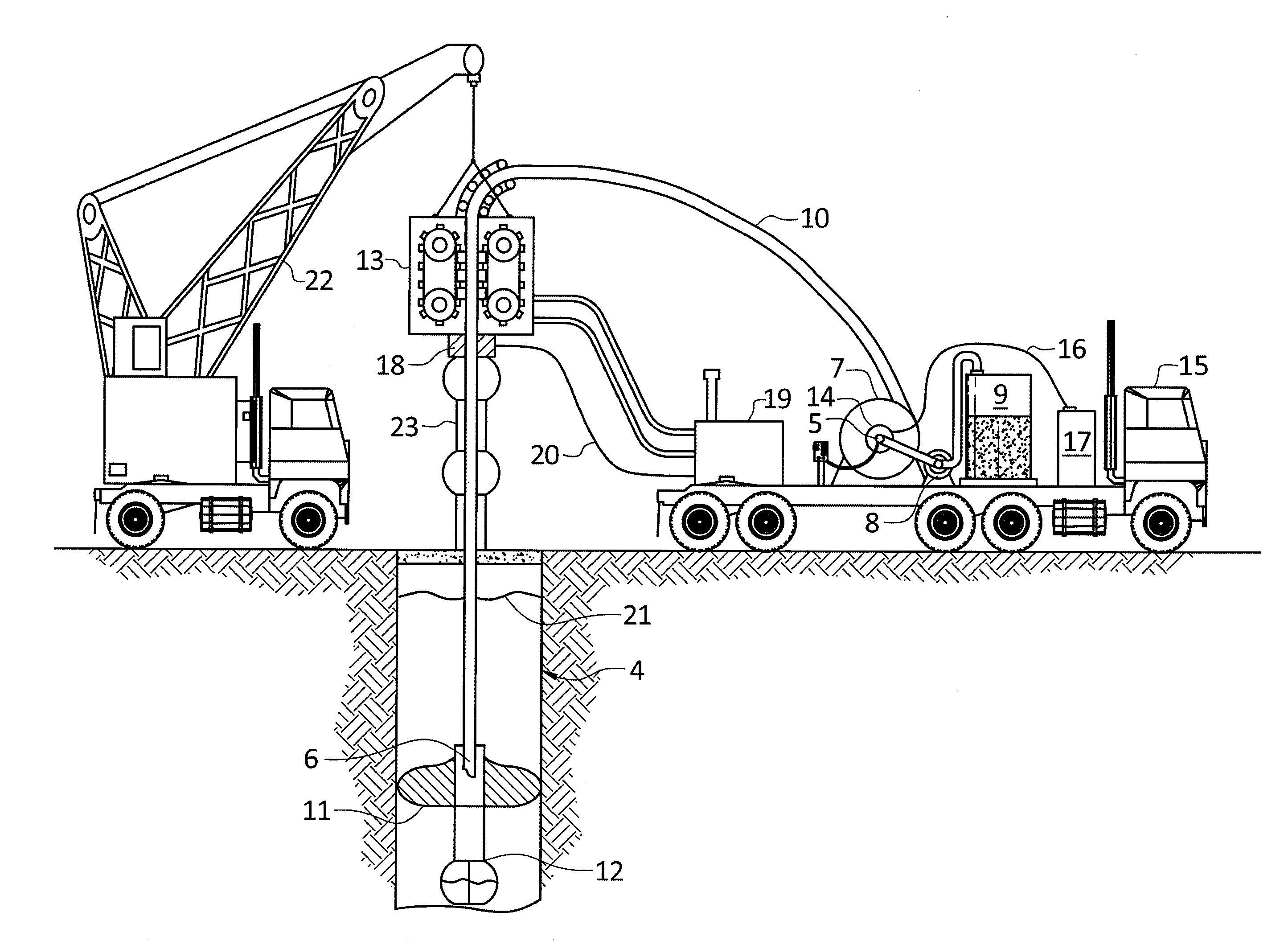
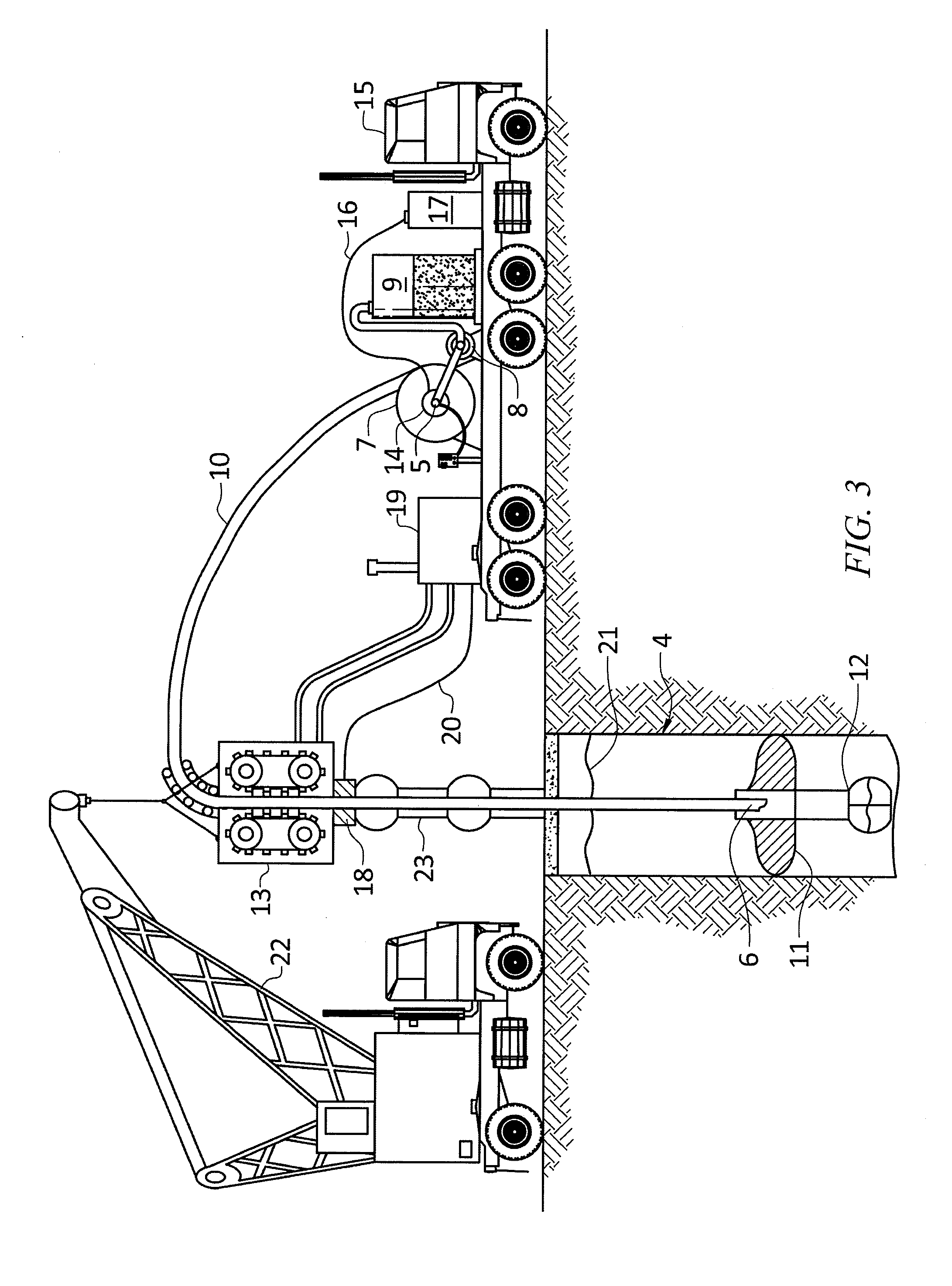
For example, in ultra-deep wells a dual drum capstan surface logging system must be deployed as the collapse forces and loads on the inner most electrical wire line logging cable wraps on the capstan drum of a simple single capstan system become too great and fail the material of the electrical cable and insulation braided inside the steel wire rope of today's logging systems.
This dual drum system is very expensive and its large foot print poses challenges on offshore platforms, rigs, and vessels.
Moreover, the inability to repair current electrical wire line logging cables containing multiple braided steel wire rope and steel tube as strength members for the logging cables power and signal transmission members made from copper and silicon dioxide is largely prohibitive.
These arrangements make repair difficult, as splicing and other repair operations involving copious numbers of braided strength wires, tubes and transmission members in a section of electric wire line logging cable becomes difficult, time consuming, and as a result, costly.
Hence large amounts of logging line per year are disposed as waste due to the difficulties and costliness of repairing it.
The operators of such cable systems typically remove and discard, from the distal end of the electric wire line logging cable hundreds of feet or more after each operation, which is continually compromised during use.
Wire logging line becomes compromised by the auto-gyro affect caused from well logging and the resulting cold working and fatigue stressing induced on the cables.
Therefore due to the configuration of the currently used logging wire line cables, the cable is inherently damaged in normal operations and there are no quick and inexpensive ways to repair the wire line.
It should be noted that while distal portion of current arts logging wire line cable are most often compromised, all portions are subject to fatigue, and wear damage to well gases and liquids having deleterious effects on electrical cable and steel braided wires of the cable.
This auto-gyro twisting phenomena presented by well bores and current logging line systems is a further detriment to the disposal and use of optical fiber within the current wire line configurations for well logging cables.
The stretch and twist resistance of optical fibers of the current state of the art logging cables causes severe damage to the optical fibers resulting in large quantities of optical fibers in such logging lines to be broken.
Steel wire has vastly different thermal coefficients of thermal expansion and elastic stretch before deformation as opposed to optical fiber, hence current methods of disposing optical fiber in wire lines made of steel is limiting the use of optical fibers.
Once this occurs the current state of the art does not teach towards repairing or replacement of the logging line nor the optical fiber therein and damaged optical fiber in braided wire line logging cables is discarded as waste.
Therefore, the current state of the art offers no commercial means to repair the optical fiber in a broken electrical wire line cable system, nor does it present a logging line system amenable to the differences between optical fiber and steel wire to enhance the life of the optical fibers.
Optical fibers in the current art logging lines fail for many reasons including hydrogen darkening, neutron bombardment, different thermal coefficients of expansion between the optical fiber and the current arts steel wire rope systems, and impacts loads that can shatter the optical fiber like those that occur during perforating.
Hence copper electrical cable is not sufficiently strong to hang or deploy in a well or in deep offshore cable systems from platforms to the sea floor, as it cannot sustain its own weight to depths much beyond approximately 3,000 feet.
Moreover, in well logging operations cannot support the weight of hanging a suite of subterranean logging tools, nor tensile or torque loads induced on logging cables in wells, or marine water depths where currents can cause continual movement of submersible cables.

Method used


Image

  • Method and apparatus for a subterranean and marine-submersible electrical transmission system for oil and gas wells
  • Method and apparatus for a subterranean and marine-submersible electrical transmission system for oil and gas wells
  • Method and apparatus for a subterranean and marine-submersible electrical transmission system for oil and gas wells

Examples


Embodiment Construction

[0049]As used herein, “a” or “an” means one or more. Unless otherwise indicated, the singular contains the plural and the plural contains the singular. For example, as used herein, the term “logging tool” includes both a single logging tool and more than one logging tools arranged in any way, such as a suite of logging tools. Where an apparatus is said to comprise a logging tool, that apparatus should be understood include a single logging tools or a suite of logging tools. As used herein, unless otherwise indicated or otherwise clear from the context, the word “or” includes both the conjunctive and the disjunctive and means “and or”, sometimes written as “and / or”. Thus, the phrase “transmission of electrical power or data”, should be understood to mean “transmission of electrical power and / or data”. Thus, the present invention therefore encompasses all three of the following: 1) conduits for transmission of both electrical power and data, 2) conduits for transmission of electrical ...


PUM

PropertyMeasurementUnit
yield strengthaaaaaaaaaa
lengthaaaaaaaaaa
densityaaaaaaaaaa

Abstract

The present invention is directed towards methods of oil and gas well logging, monitoring, and the field of electrically powering submersible devices like electrical motors in oil and gas wells.

Description

CROSS-REFERENCE TO RELATED APPLICATIONS[0001]This application claims priority to U.S. provisional patent application Ser. No. 61 / 318,182, filed on Mar. 26, 2010.TECHNICAL FIELD[0002]The present invention is directed to a method and apparatus for a marine-submersible and subterranean electrical transmission systems for oil and gas wells and marine applications. More specifically, this invention overcomes previous shortcomings of submersible logging cables by teaching methods and apparatus to construct submersible electrical transmission systems using novel methods of manufacturing, and well logging. The invention includes methods and apparatus for well logging lines that have synergistic electrical, hydraulic, and structural functionality vastly superior to the current oil and gas industry wire line methods. The invention provides a new way to achieve superior line durability, reparability, safety, hydraulic functionality, and optical functionality as opposed to current methods known...

Claims


Application Information

Patent Timeline
Patent Type & Authority Applications(United States)
IPC IPC(8): G01V3/00H01B7/00
CPCE21B47/122H01B1/02H01B7/046H01B3/004H01B1/026E21B47/13
Inventor SMITH, DAVID RANDOLPH
Owner SMITH DAVID RANDOLPH
Why Eureka
Try Eureka