Fan

a fan and fan body technology, applied in the field of portable fans, can solve the problems of inability to carry, time-consuming cleaning of bladed fans, etc., and achieve the effect of facilitating the connection of the filter uni

Inactive Publication Date: 2011-09-29
DYSON TECH LTD
View PDF32 Cites 57 Cited by
  • Summary
  • Abstract
  • Description
  • Claims
  • Application Information

AI Technical Summary

Benefits of technology

[0015]The casing may have a first connector, and the air outlet may have a second connector. The filter unit may include a third connector, which is substantially the same as the second connector, for co-operating with the first connector to removably connect the filter unit to the casing, and a fourth connector, which is substantially the same as the first connector, for co-operating with the second connector to removably connect the air outlet to the filter unit. This can allow the air outlet to be connected either directly to the casing, or for the filter

Problems solved by technology

The cleaning of bladed fans can be time consuming for the employee, as the cage housing the blades of the fan needs to be disassembled before the blades of the fan can be cleaned.
This disassembly usually requires the use of

Method used


Image

  • Fan
  • Fan
  • Fan

Examples


Embodiment Construction

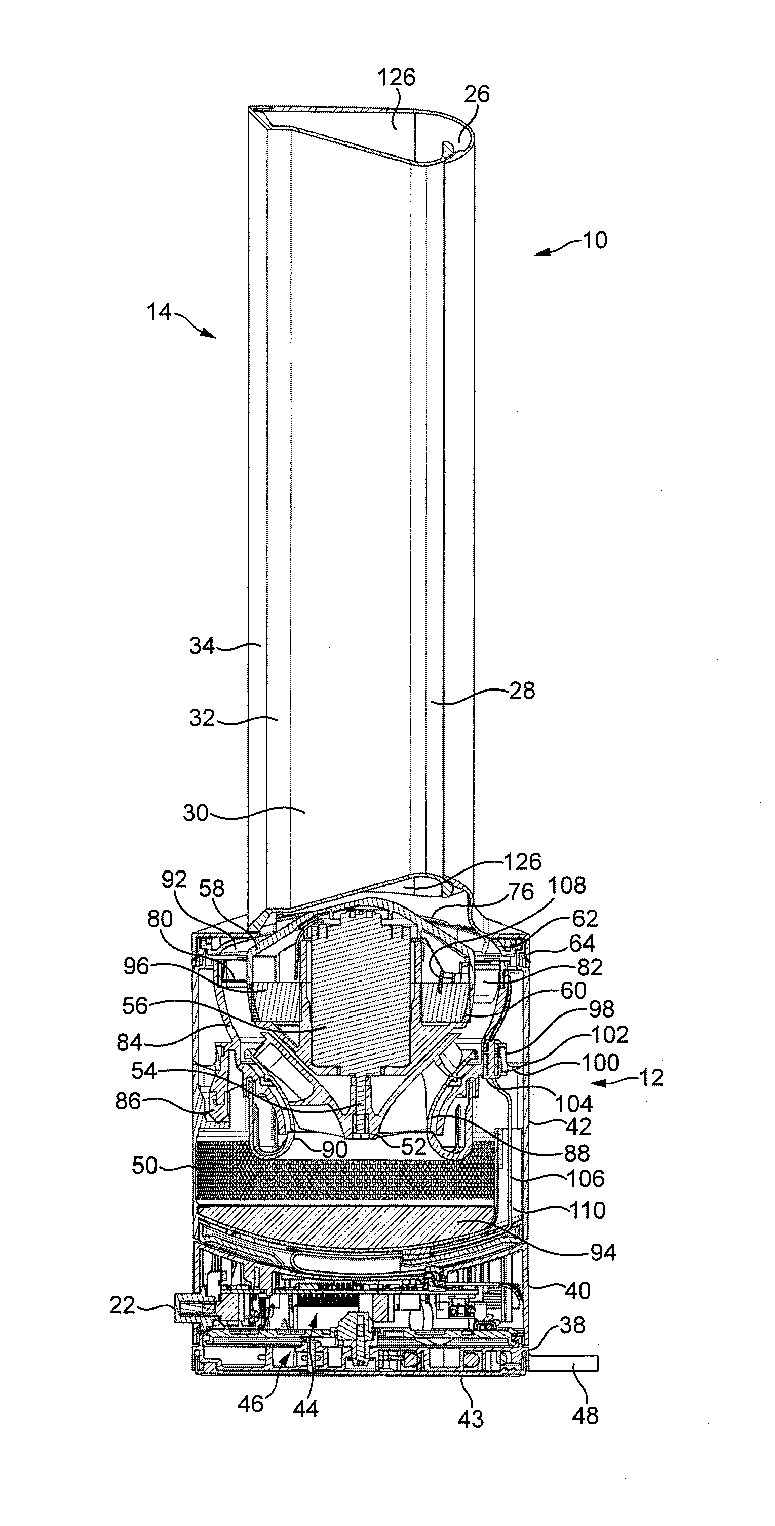
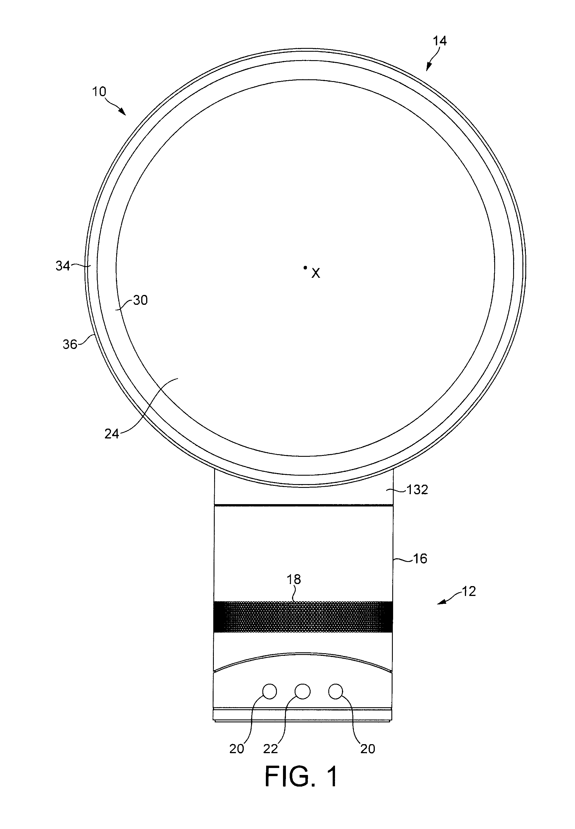
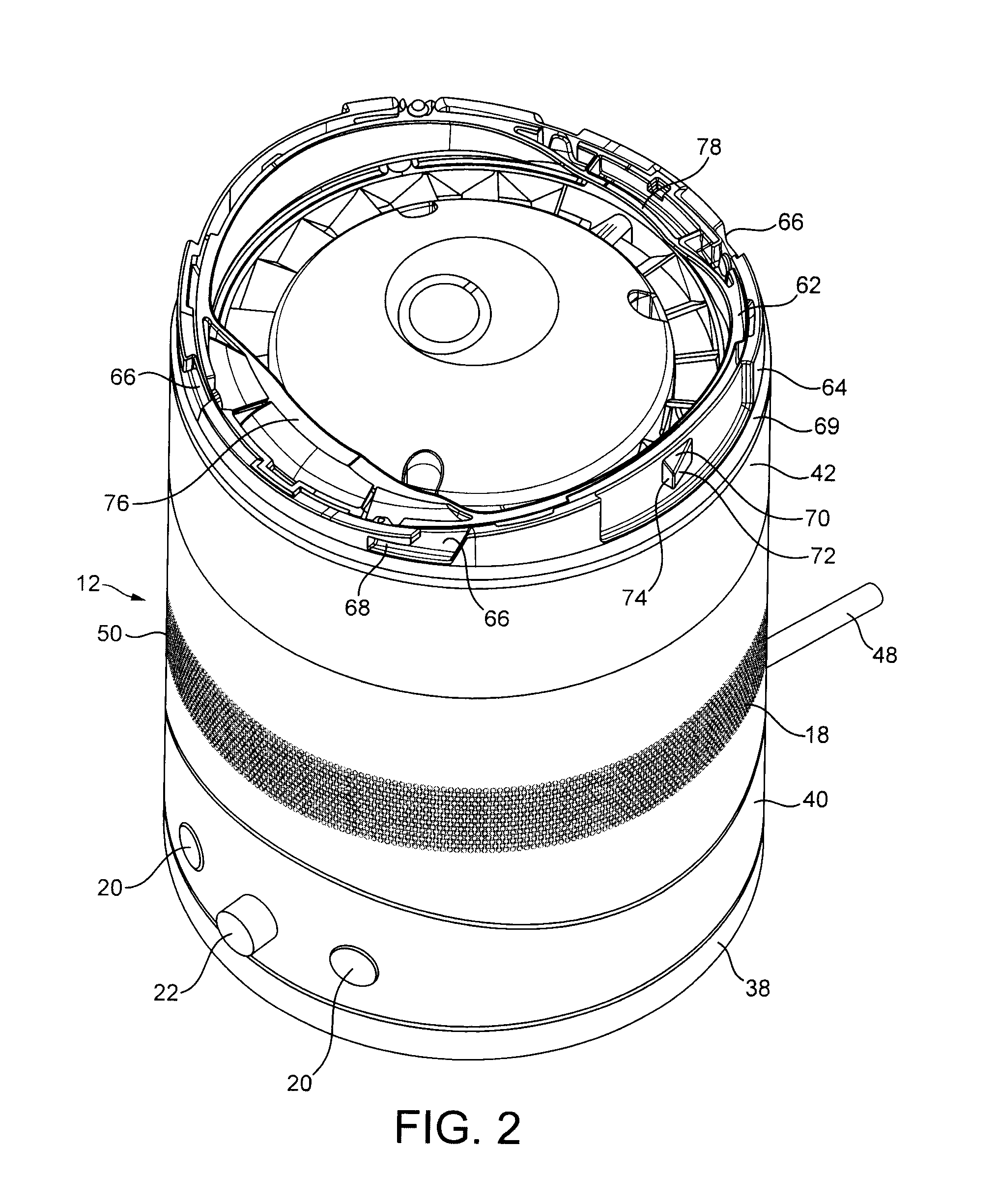
[0028]FIG. 1 is a front view of a fan 10. The fan 10 is preferably in the form of a bladeless fan 10 comprising a base 12 and an air outlet 14 connected to the base 12. With reference also to FIG. 2, the base 12 comprises a substantially cylindrical outer casing 16 having a plurality of air inlets 18 in the form of apertures formed in the outer casing 16 and through which a primary air flow is drawn into the base 12 from the external environment. The base 12 further comprises a plurality of user-operable buttons 20 and a user-operable dial 22 for controlling the operation of the fan 10. In this example the base 12 has a height in the range from 200 to 300 mm, and the outer casing 16 has an external diameter in the range from 100 to 200 mm.

[0029]As shown in FIG. 3, the air outlet 14 has an annular shape and defines an opening 24. The air outlet 14 has a height in the range from 200 to 400 mm. The air outlet 14 comprises a mouth 26 located towards the rear of the fan 10 for emitting a...


PUM


Abstract

A portable fan includes a casing having an air inlet, and an air outlet having an interior passage for receiving an air flow, and a mouth for emitting the air flow, the interior passage extending about an opening through which air is drawn by the air flow emitted from the mouth. The fan includes an impeller and a motor for rotating the impeller to generate an air flow between the air inlet and an air outlet which has a static pressure of at least 150 Pa downstream from the impeller. A filter unit is detachably connected to the casing. A filter of the filter unit is located upstream of the air inlet to remove airborne particulates from the air flow before it enters the casing.

Description

REFERENCE TO RELATED APPLICATIONS[0001]This application claims the priority of United Kingdom Application No. 1004813.0 filed Mar. 23, 2010, the entire contents of which are incorporated herein by reference.FIELD OF THE INVENTION[0002]The present invention relates to a portable fan. Particularly, but not exclusively, the present invention relates to a floor or table-top fan, such as a desk, tower or pedestal fan.BACKGROUND OF THE INVENTION[0003]A conventional domestic fan typically includes a set of blades or vanes mounted for rotation about an axis, and drive apparatus for rotating the set of blades to generate an air flow. The movement and circulation of the air flow creates a ‘wind chill’ or breeze and, as a result, the user experiences a cooling effect as heat is dissipated through convection and evaporation. The blades are generally located within a cage which allows an air flow to pass through the housing while preventing users from coming into contact with the rotating blades...

Claims


Application Information

Patent Timeline
IPC IPC(8): F04B53/20
CPCF04D25/084F04D29/703F04D29/646F04D29/626F04F5/16F04D25/08F04F5/44F05D2260/33F24F1/022F24F1/04F24F13/28
Inventor FITTON, NICHOLAS GERALDSIMMONDS, KEVIN JOHN
Owner DYSON TECH LTD
Why Eureka
Try Eureka