Systems and methods for preventing or reducing contamination enhanced laser induced damage (c-lid) to optical components using gas phase additives

a technology of enhanced laser and gas phase additives, which is applied in the field of preventing or reducing contamination laser induced damage to optical components, can solve the problems of longer life of optical components, achieve greater affinity for optical components, prevent or reduce contamination enhanced laser induced damage (c-lid), and reduce or eliminate the effect of optic degradation

Active Publication Date: 2011-09-29
THE AEROSPACE CORPORATION
View PDF18 Cites 13 Cited by
  • Summary
  • Abstract
  • Description
  • Claims
  • Application Information

AI Technical Summary

Benefits of technology

Embodiments of the present invention provide gas phase additives to prevent or reduce Contamination Enhanced Laser Induced Damage (C-LID) to optical components. Specifically, the gas phase additive may have a greater affinity for the optical component than does the contaminant, and may be present in an amount (e.g. a partial pressure) selected such that the additive inhibits binding of the contaminant to the surface of the optical component. For example, the additive may be present in an amount selected to substantially cover the surface of the optical component, leaving substantially no area for the contaminant to adsorb or absorb to the surface. The additive thus may reduce or eliminate degradation of the optic through mechanisms such as light transmission loss, increased light scatter, and obscuration. The inhibited degradation may result in longer life for the optical component.

Problems solved by technology

The inhibited degradation may result in longer life for the optical component.

Method used


Image

  • Systems and methods for preventing or reducing contamination enhanced laser induced damage (c-lid) to optical components using gas phase additives
  • Systems and methods for preventing or reducing contamination enhanced laser induced damage (c-lid) to optical components using gas phase additives
  • Systems and methods for preventing or reducing contamination enhanced laser induced damage (c-lid) to optical components using gas phase additives

Examples


example

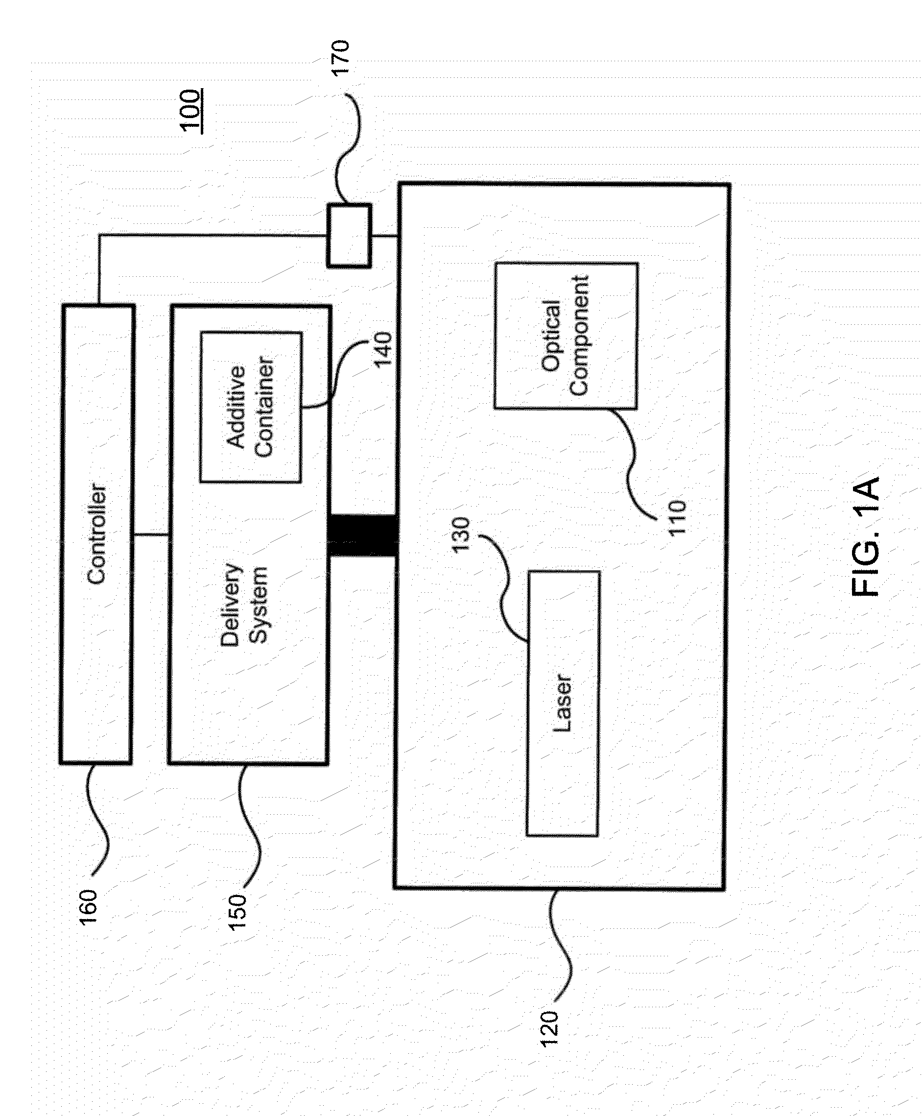
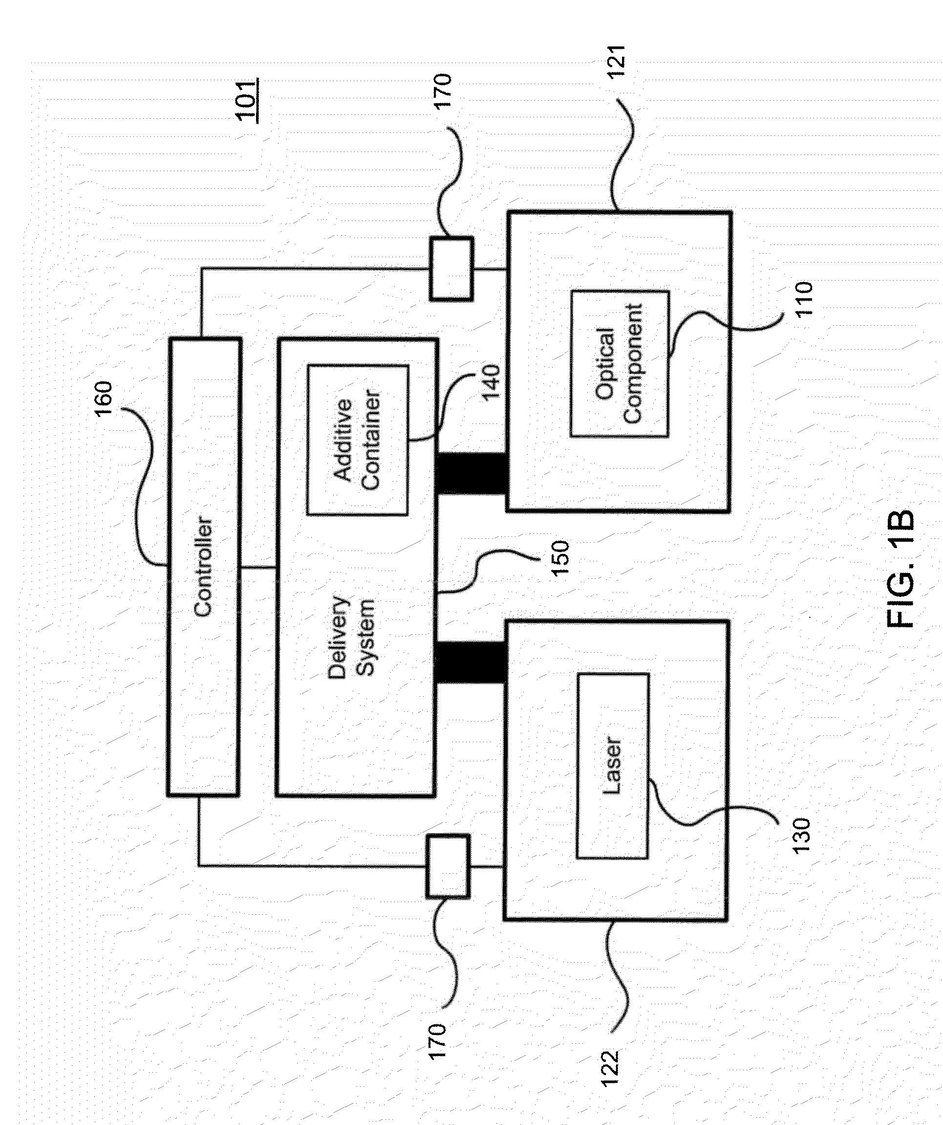
The functionality of devices 100, 101, and 102 and method 200 for reducing C-LID to an optical component in a housing may be illustrated by way of Example as described below.

1. Experimental Set-Up

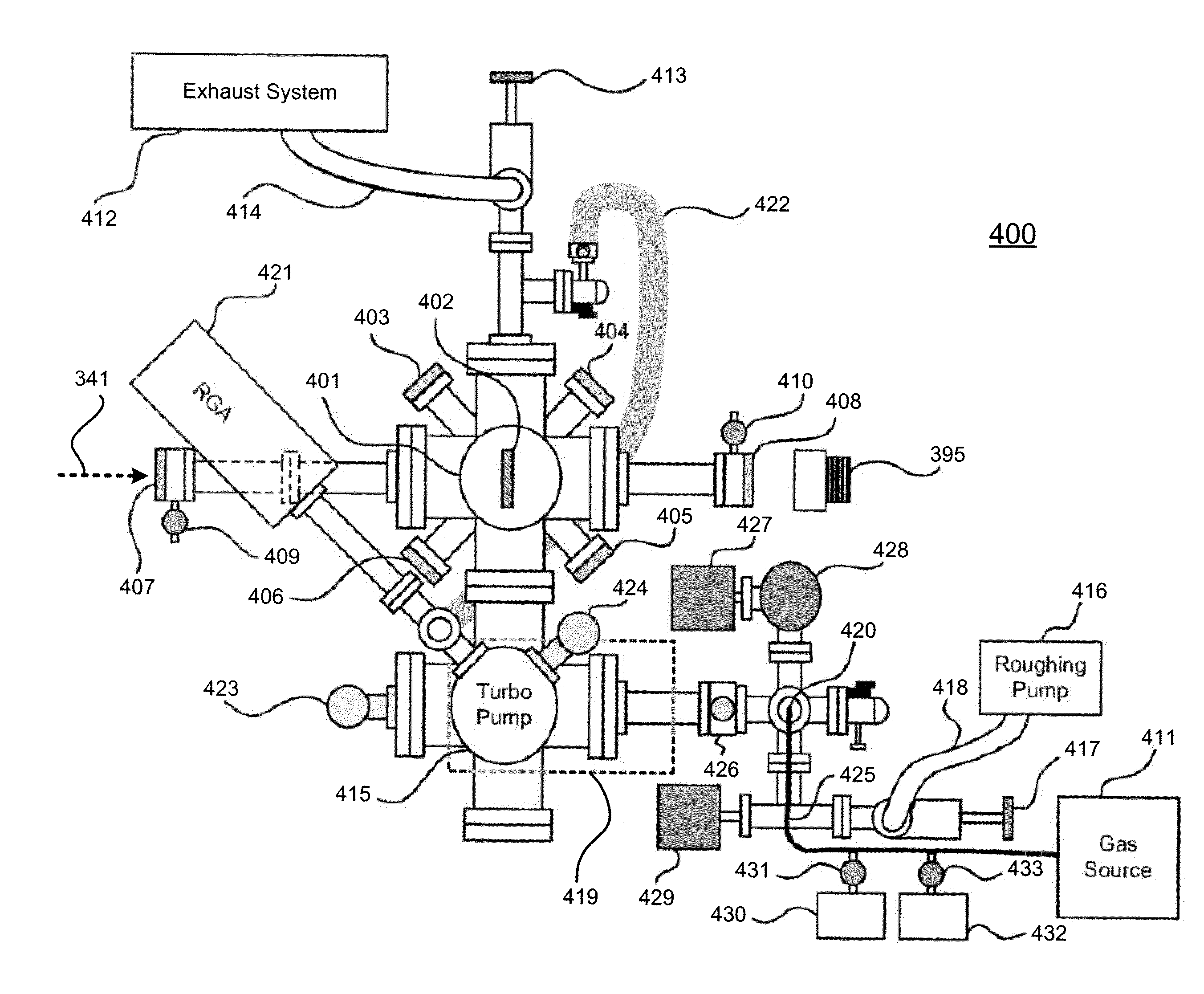
FIG. 3 is a schematic view of C-LID test apparatus 300, which may be used to measure Laser Induced Damage Threshold (LIDT) and the extent of C-LID on bare fused silica substrates in vacuum conditions. Apparatus 300 includes Helium Neon (HeNe) laser 310, which generates HeNe laser beam 311; mirrors 320, 321, 322; Nd:YAG laser 330, which generates Nd:YAG laser beam 331; dichroic beam splitter 340; energy meters 350, 395; irises 360, 361; high-power laser mirrors 370, 371, 390; telescope 380; and test chamber 400 which, as described in greater detail below, contains the bare fused silica substrate.

The laser beams in apparatus 300 were aligned before entering test chamber 400. HeNe laser 310 emits HeNe laser beam 311. Mirrors 320, 321, 322 reflect HeNe laser beam 311 to an appropriate point on ...


PUM

PropertyMeasurementUnit
partial pressureaaaaaaaaaa
diameteraaaaaaaaaa
diameteraaaaaaaaaa

Abstract

Systems and methods for preventing or reducing contamination enhanced laser induced damage (C-LID) to optical components are provided including a housing enclosing an optical component, a container configured to hold a gas phase additive and operatively coupled to the housing; and a delivery system configured to introduce the gas phase additive from the container into the housing and to maintain the gas phase additive at a pre-selected partial pressure within the housing. The gas phase additive may have a greater affinity for the optical component than does a contaminant and may be present in an amount sufficient to inhibit laser induced damage resulting from contact between the contaminant and the optical component. The housing may be configured to maintain a sealed gas environment or vacuum.

Description

FIELD OF THE INVENTIONThis application generally relates to preventing or reducing contamination laser induced damage to optical components.BACKGROUND OF THE INVENTIONIt is well known that laser beams may in some circumstances damage optical materials and coatings. Referred to as Laser Induced Damage (LID), it is believed that damage to optical materials may stem from the direct interaction of photons with the material. In particular, it is believed that the electric field component of the laser radiation may interact with surface defects, leading to thermal breakdown. The decomposition of the material may lead to pitting or carbon formation, which in turn may lead to increased material damage and rapid failure of the optic.To mitigate LID, optical materials that are relatively tolerant to laser damage may be selected for use in laser technologies. After the optical materials are selected, screening tests that are specific to a particular system are conducted. Typically, the tests i...

Claims


Application Information

Patent Timeline
Patent Type & Authority Applications(United States)
IPC IPC(8): B05C11/10B05D5/06
CPCB23K26/123B23K26/127B23K26/12H01S3/2391H01S3/2222Y10T137/0318Y10T137/8593
Inventor WEILLER, BRUCE H.VILLAHERMOSA, RANDY M.FOWLER, JESSE D.
Owner THE AEROSPACE CORPORATION
Why Eureka
Try Eureka