
Valve Actuator Having Synchronous Motor Having Plastic Bushings

a technology of synchronous motors and valve actuators, which is applied in the direction of synchronous motors, valve operating means/release devices, mechanical devices, etc., can solve the problems of valve actuators not being able to fix, and not being able to return to normal state. , to achieve the effect of reducing frictional problems, preventing corrosion, and reducing the issue of fretting corrosion

Inactive Publication Date: 2011-10-06
SCHNEIDER ELECTRIC BUILDINGS LLC
View PDF8 Cites 42 Cited by
  • Summary
  • Abstract
  • Description
  • Claims
  • Application Information

AI Technical Summary

Benefits of technology

[0022]Because the material is corrosion rather than straight worn material, the corroded surfaces, oxides, form a light bond with the rest of the material that can be easily wiped away from the rest of the shaft or bearings. During the fretting action, the oxide, unlike the standard base material, could be easily wiped away, as opposed to what would be required for normal wear. As the powder oxide is wiped away, more surface is exposed to promote further corrosion. As the corrosion was continuously wiped away more and more corrosion was occurring and increasing the friction between the shaft and the bearings. Further, corrosion promotes the sticking problem more than straight wear because corrosion has a larger volume than straight wear due to the inclusion of the oxygen molecules thereby more quickly packing the space between the shaft and the bearings with powder particulates increasing the frictional forces.
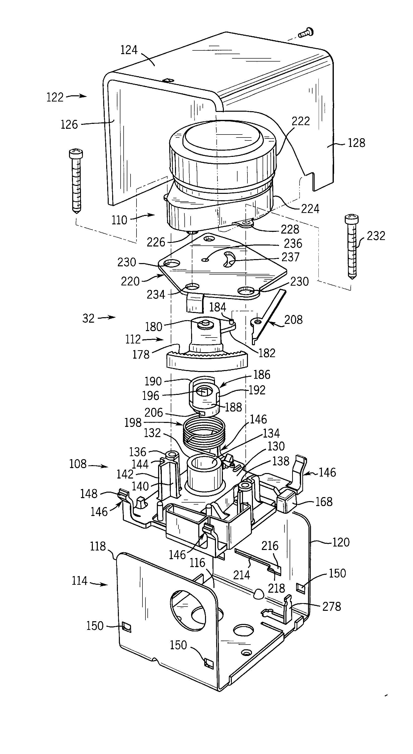
[0033]The synchronous motor also includes a magnetic coil for generating alternating magnetic flux. The motor includes a stator arrangement including a magnetic hub surrounded by the magnetic coil. The stator arrangement also includes an upper disc and a lower disc attached proximate a first end of the magnetic hub. The upper disc includes upper radially extending pole pieces and the lower disc includes lower radially extending pole pieces. The upper and lower radially extending pole pieces alternating angularly. An undulating shielding disc is interposed between adjacent upper and lower radially extending pole pieces. The undulating shielding disc passes above the lower radially extending pole pieces and below the upper radially extending pole pieces shading the upper pole pieces. The stator includes a set of shielded and set of unshielded axially extending pole pieces and an undulating shielding ring interposed between adjacent ones of the shielded and unshielded pole pieces such that the shielding ring passes over a radially outer surface of the unshielded axially extending pole pieces and radially inward of a radially inner surface of the shielded axially extending pole pieces. The synchronous motor further includes a rotor including a rotor shaft coupled to an annular magnetic flange. The magnetic hub includes a pair of plastic bearings mounted therein to reduce corrosion effects due to fretting corrosion when the motor is in a stalled state. The rotor shaft passes through central apertures of the plastic bearings and is supported for rotation therein. The annular magnetic flange is positioned within an annular channel formed between the axially extending pole pieces and the radially extending pole pieces.

Problems solved by technology

The Applicant of the instant application has determined significant problems related to this valve design, and particularly, with the use of the synchronous motors to maintain the valves in the non-normal state for extended periods of time.
The Applicant has determined numerous problems with the prior art designs that have caused these valves to stick in the non-normal state such that the valve actuator cannot return to the normal state once power is removed from the motor.
Further, when the Applicant addressed this sticking problem with the leading manufacturer in the industry, the industry leader indicated that they have been working on fixing this problem on and off for many years but have not been able to fix it.
The powder increases the friction between the rotor shaft and the bearings such that the spring cannot return the actuator to the normal state.

Method used


Image

  • Valve Actuator Having Synchronous Motor Having Plastic Bushings
  • Valve Actuator Having Synchronous Motor Having Plastic Bushings
  • Valve Actuator Having Synchronous Motor Having Plastic Bushings

Examples


Embodiment Construction

[0062]The present invention relates to improvements in valves that utilize electrical actuators, such as disclosed in U.S. Pat. No. 6,073,907, to the assignee of the instant application. An introduction of the operation of those valves will be provided first and then a discussion of the motor used within the actuators thereof will be provided.

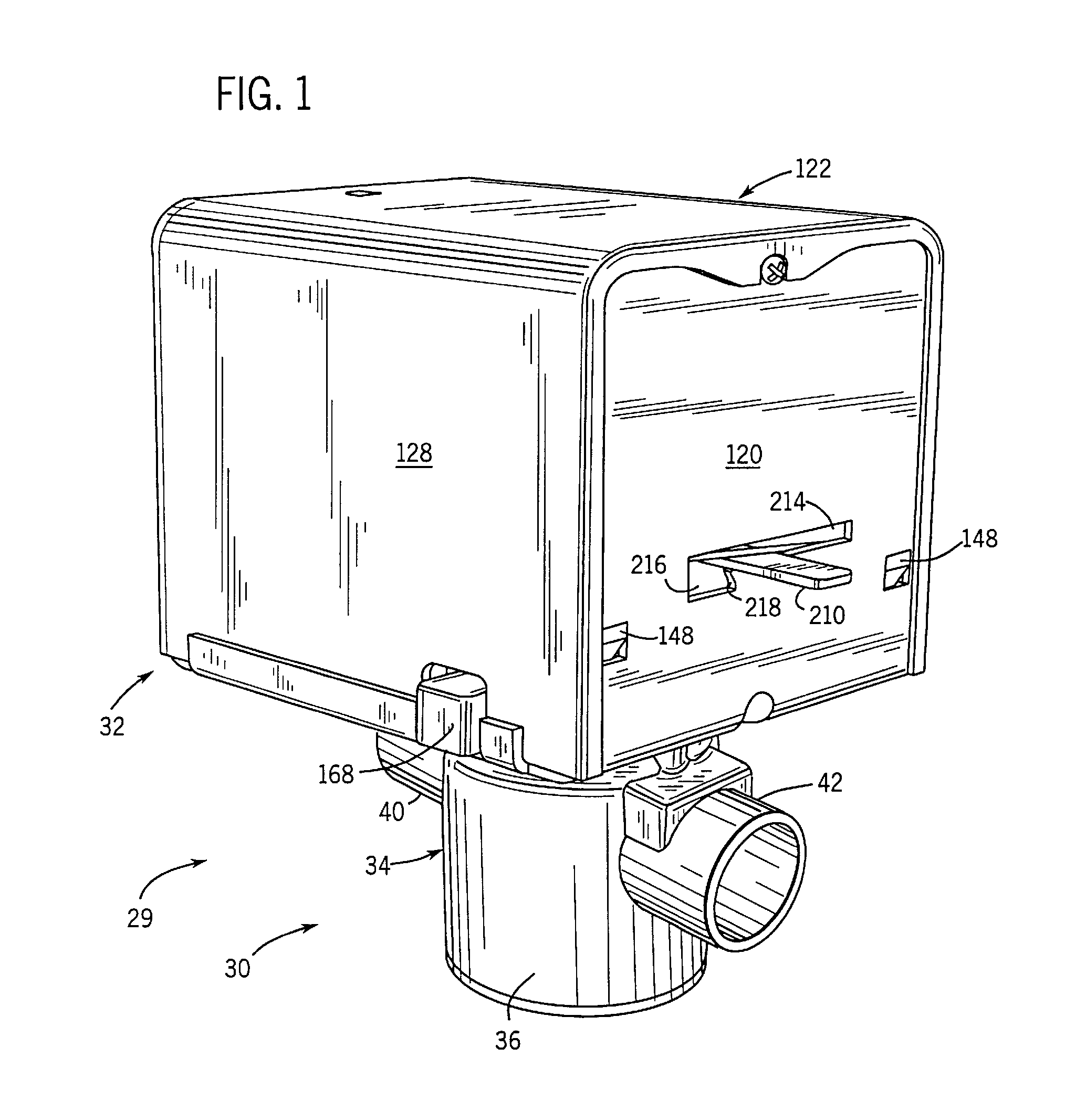
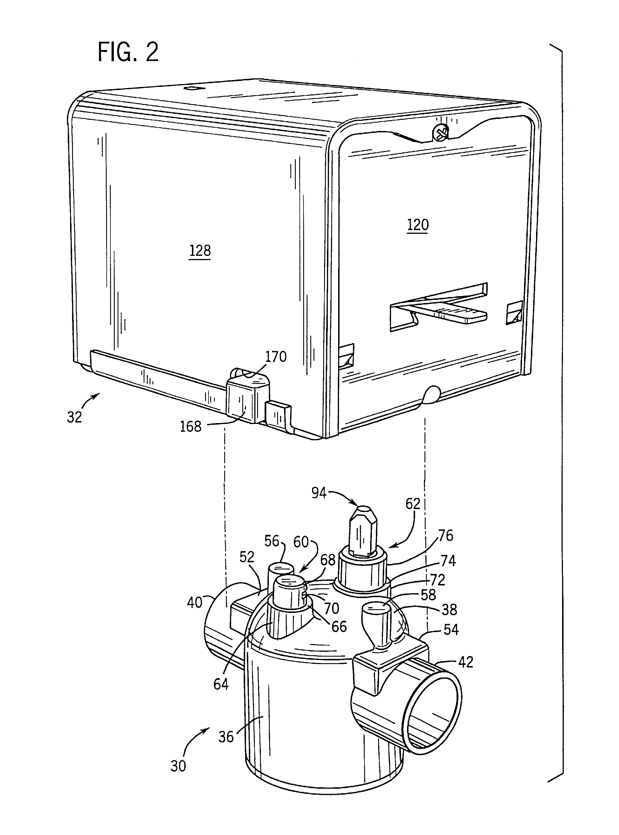
[0063]With that introduction, FIG. 1 illustrates a valve assembly 29 including a valve body 30 and a valve actuator assembly 32. Valve body 30 includes a central body portion 34 defined by a peripheral sidewall 36 and a domed upper wall 38 (FIG. 2). A pair of nipples 40, 42 extend from sidewall 36. Nipples 40, 42 are adapted to be plumbed into a fluid flow line, such as a line used in a water-operated heating system or in any other application requiring regulation of fluid flow in the line.

[0064]As shown in FIG. 4, nipple 40 defines an outlet passage 44 and nipple 42 defines an inlet passage 46 having an inner restricted portion 47. Passages 44...


PUM


Abstract

A synchronous motor and a valve having a valve actuator and valve assembly is provided. The valve actuator includes the synchronous motor. The synchronous motor utilizes a magnetic coil, a stator and a rotor to generate rotational movement to drive the valve member for the valve assembly. The valve has a normal state in which the valve is maintained when power is not supplied to the motor. The valve has a non-normal actuated state when power is supplied to the motor. The motor is stalled in the non-normal state to maintain the valve in that state. The rotor includes a rotor shaft that passes through a magnetic hub of the stator. The rotor shaft is supported by a plurality of plastic and / or nylon bearings to prevent corrosion therebetween when the rotor shaft and bearings remain in a substantially fixed orientation for an extended period of time.

Description

FIELD OF THE INVENTION[0001]This invention generally relates to valve actuators and synchronous motors and more particularly to valve actuators using synchronous motors.BACKGROUND OF THE INVENTION[0002]Valves are used in a variety of applications to control fluid flow. Typically, a valve includes a movable valve member disposed within an internal passage or cavity in communication with a fluid line, and the valve member is movable in response to an actuator to vary the position of the valve member to control the flow of fluid in the line.[0003]One type of valve utilizes a valve body adapted to be plumbed into a line, to which a valve member is mounted for movement through a range of operating positions to control flow of fluid through the valve body in response to operation of an actuator assembly. Typically, the valve member is movable between an open position and a closed position, and the valve member is mounted to an operating member such as a valve stem, which in turn is pivota...

Claims


Application Information

Patent Timeline
IPC IPC(8): F16K31/04F16K51/00H02K21/24
CPCH02K5/1675H02K7/116F16K31/043H02K37/02F16K31/042H02K19/06
Inventor WINDGASSEN, WILLIAM P.
Owner SCHNEIDER ELECTRIC BUILDINGS LLC
Learn More