Determining the rotor angle of a synchronous machine at standstill with the aid of iterative test pulses

a technology of synchronous machines and test pulses, applied in the direction of motor/generator/converter stoppers, dynamo-electric converter control, instruments, etc., can solve the problems of affecting the accuracy of synchronous machines, etc., to achieve the effect of simple evaluation mechanisms and small investmen

Active Publication Date: 2011-10-06
ROBERT BOSCH GMBH
View PDF4 Cites 7 Cited by
  • Summary
  • Abstract
  • Description
  • Claims
  • Application Information

AI Technical Summary

Benefits of technology

[0010]It is, therefore, an object of the present invention to devise a mechanism for precisely sensing the absolute angular position for electric motors that is able to be realized with little outlay for electrical components and using simple evaluation mechanisms.

Problems solved by technology

Under certain circumstances, a deviation of only a few degrees can result in a very pronounced difference with respect to the torque.
The use of separate sensors entails additional space, additional costs, separate supply leads, and additional manufacturing steps, etc.
Moreover, additional components have the inherent risk of generally being associated with additional sources of error.
On the one hand, the method is costly since the angular position is based on the combination of a multiplicity of various rise times that are indicative of the particular saturation, and, on the other hand, since the resolution is defined by the angular offset of two different stator windings, i.e., 60°, for example.
In addition, inaccuracies in the position can result at locations where the inductance only changes slightly with the angle, i.e., at + / −90°, for example.
Therefore, the absolute angle sensing methods mentioned above in the context of stationary electric motors are associated, on the one hand, with additional components, or they entail a costly calculation and, at the same time, are prone to a reduced accuracy and a high fault rate due to external stray fields.
In particular, interpolation-based angle acquisitions require a considerable outlay for complex calculations; even in the case of minor measurement errors, the interpolation also leading to substantial angular errors.

Method used


Image

  • Determining the rotor angle of a synchronous machine at standstill with the aid of iterative test pulses
  • Determining the rotor angle of a synchronous machine at standstill with the aid of iterative test pulses
  • Determining the rotor angle of a synchronous machine at standstill with the aid of iterative test pulses

Examples


Embodiment Construction

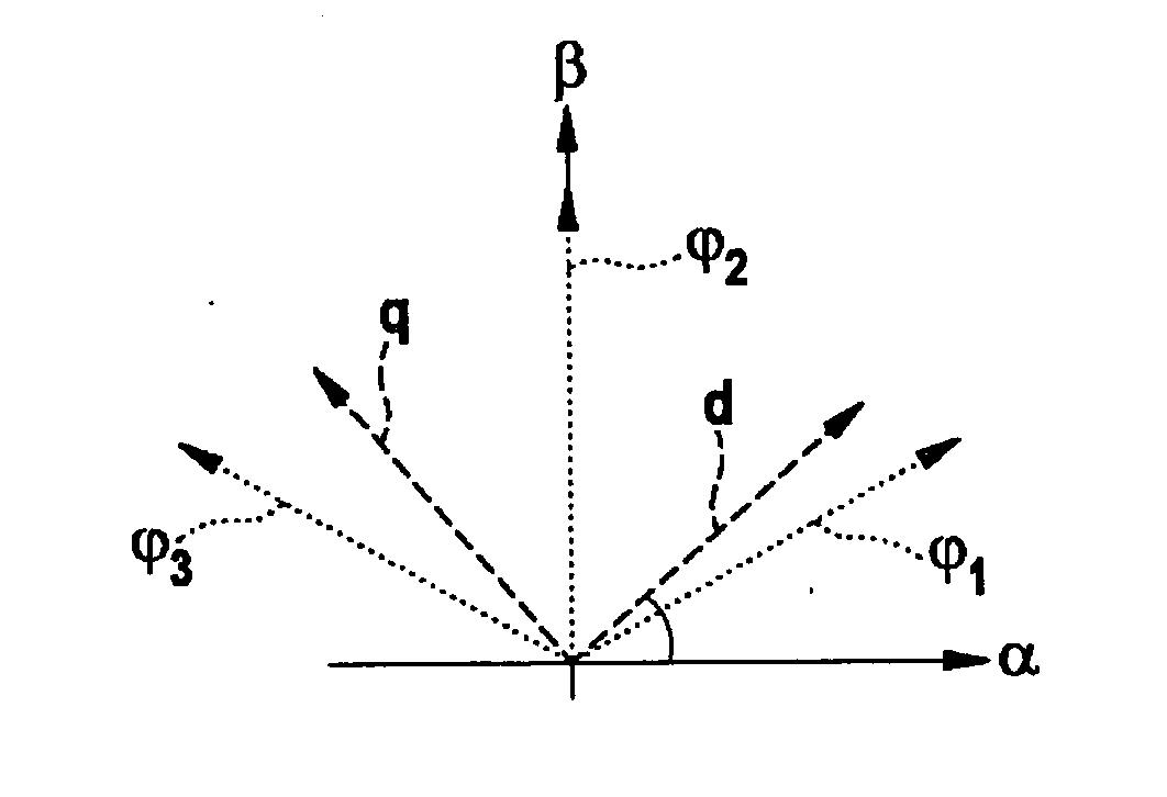
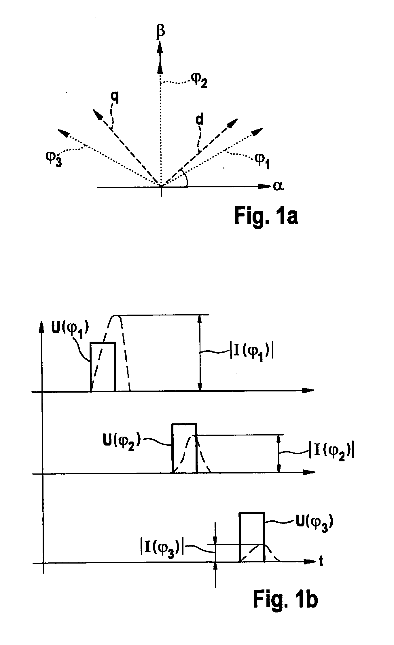
[0040]FIG. 1a shows the initialization of the method according to the present invention with reference to a circuit diagram that is based on a rotor having a north and a south pole. The main magnetization direction, thus the field lines of the magnetic field produced by an excitation coil, extends along the axis characterized by d. The q-axis extends orthogonally thereto and corresponds to the transversal axis which is orthogonal to longitudinal axis d, the q-axis extending orthogonally to the field lines of the excitation magnetic field. Initially, the angular directions that are each offset by 60° from one another are scanned in accordance with the active scanning method, i.e., in that a voltage pulse is emitted in each of directions φ1, φ2 and φ3. In other words, three different voltage pulses are transmitted to the stator, which, as a result, generates three different magnetic fields in directions φ1, φ2 and φ3. The corresponding current characteristics are recorded.

[0041]In FIG...


PUM


Abstract

A method for determining the angular position of a synchronous machine having a magnetically anisotropic rotor includes an (m) iteration stage and an (n) iteration stage. The (m) iteration stage encompasses: generating an (m) magnetic field of an (m) angular direction and acquiring an (m) peak value of the current pulse generated by the (m) voltage pulse; and providing at least two further (m+i) peak values in different (m+i) angular directions that differ from the (m) angular direction. The (n) iteration stage includes: ascertaining the angular directions (n) and (n+1) in which the two highest or the two lowest peak values from a peak value group occur; and providing an (n) angular direction, which resides between the (n+1) angular direction and the (n+2) angular direction, as an angular position output.

Description

BACKGROUND OF THE INVENTION[0001]1. Field of the Invention[0002]The present invention is directed to angle-sensing mechanisms for electric motors and, in particular, for synchronous machines.[0003]2. Description of Related Art[0004]Electric motors are used for a multiplicity of applications; depending on the particular use, not only the speed itself, but also the rotor position being relevant. Sensing the rotor position is particularly relevant when switching on electric machines since, relative to the stator's magnetic field, the rotor position directly and significantly influences the absolute value and sign of the torque generated. Sensing the correct angle of the rotor position is particularly relevant for the operation of synchronous machines where essentially no difference in speed (“slip”) is provided between the rotor and the stator. Under certain circumstances, a deviation of only a few degrees can result in a very pronounced difference with respect to the torque. In synchr...

Claims


Application Information

Patent Timeline
Patent Type & Authority Applications(United States)
IPC IPC(8): G01B7/30
CPCH02P1/46H02P6/20H02P6/185
Inventor VOLLMER, ULRICH
Owner ROBERT BOSCH GMBH
Why Eureka
Try Eureka