Systems and methods of using subsea frames as a heat exchanger in subsea boosting systems

a technology of subsea frames and subsea boosting, which is applied in the direction of pump components, non-positive displacement fluid engines, lighting and heating apparatuses, etc. it can solve the problems of increasing the temperature of the oil in the motor of the esp, limiting the heat exchanger to the surrounding well fluid, and reducing the temperature of the dielectric lubricant. , to achieve the effect of reducing the temperature of the dielectric lubricant, reducing the cost of the a subsea frame heat exchanger and subsea frame heat exchanger and subsea frame heat exchanger and subsea subsea frame heat exchanger and subsea subsea subsea subsea subsea subsea subsea subsea subsea subsea subsea subsea subsea subsea subsea subsea subsea technology, applied subsea heat exchanger and subsea hea

Inactive Publication Date: 2011-10-13
BAKER HUGHES INC
View PDF4 Cites 11 Cited by
  • Summary
  • Abstract
  • Description
  • Claims
  • Application Information

AI Technical Summary

Benefits of technology

[0019]Advantageously, the heat removal process can be accomplished by transferring heat energy in the dielectric lubricant to seawater naturally flowing through the subsea supporting frame structure and across exterior surfaces of its elongate main structural members to thereby reduce the temperature of the dielectric lubricant. When introduced back into the confines of the housing of the motor, the cooled dielectric lubricant then functions to cool internal motor components more effectively. Thus, the life of the motor is advantageously extended and its reliability is advantageously increased.

Problems solved by technology

During operation, the temperature of the oil in the motor of the ESP increases due to mechanical friction and electrical inefficiencies.
Rejection of heat from the oil to the surrounding well fluid, however, is usually limited due to the well fluid's high temperature, and also its poor heat transfer characteristics due to its high viscosity.
An increased temperature of the motor oil due to failure to adequately dissipate heat may lead to low performance or premature failure of the motor.

Method used


Image

  • Systems and methods of using subsea frames as a heat exchanger in subsea boosting systems
  • Systems and methods of using subsea frames as a heat exchanger in subsea boosting systems
  • Systems and methods of using subsea frames as a heat exchanger in subsea boosting systems

Examples


Embodiment Construction

[0029]The present invention will now be described more fully hereinafter with reference to the accompanying drawings, which illustrate embodiments of the invention. This invention may, however, be embodied in many different forms and should not be construed as limited to the illustrated embodiments set forth herein. Rather, these embodiments are provided so that this disclosure will be thorough and complete, and will fully convey the scope of the invention to those skilled in the art. Like numbers refer to like elements throughout. Prime notation, if used, indicates similar elements in alternative embodiments.

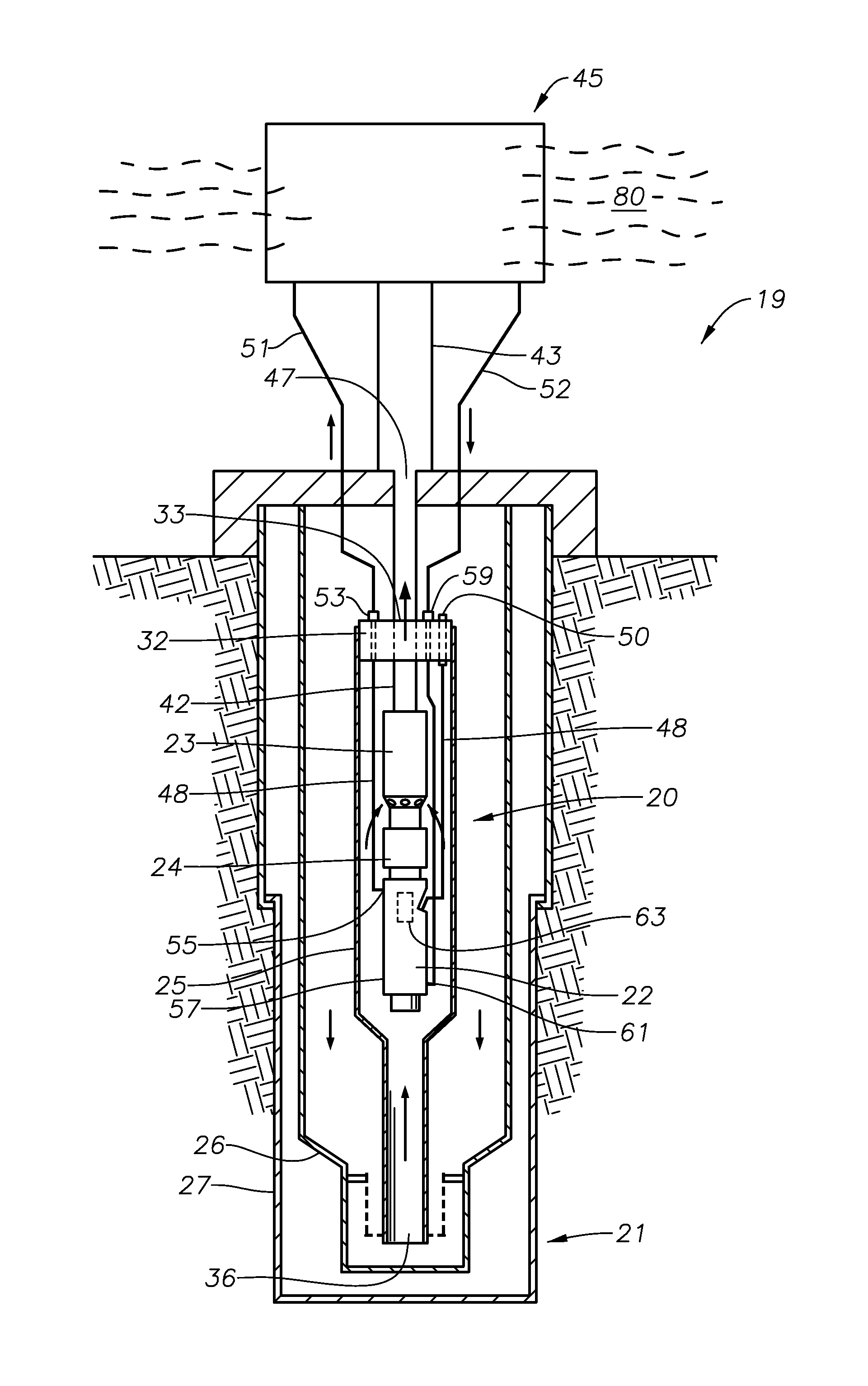
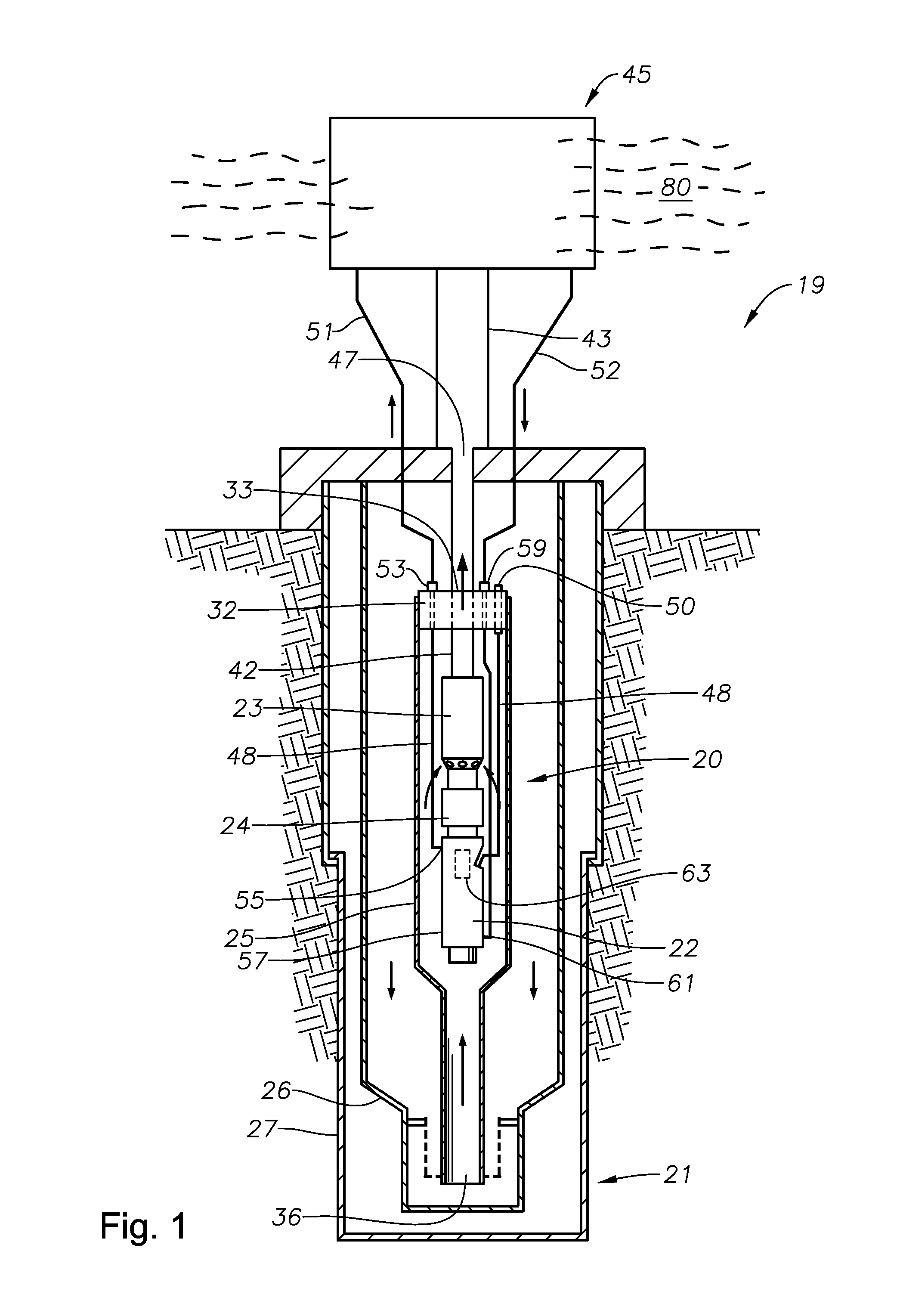
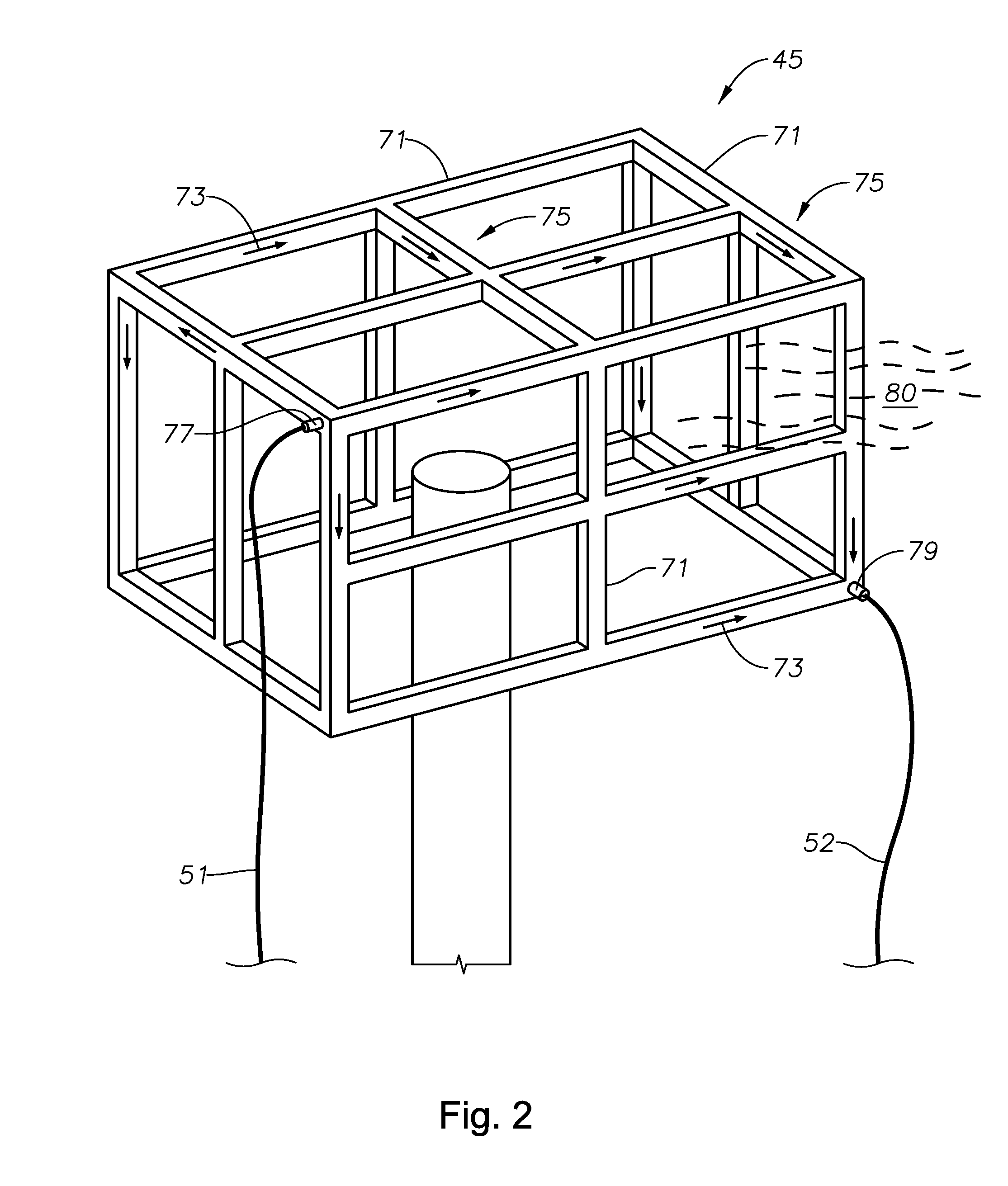
[0030]Electrical submersible pumps (ESPs) have been used for subsea boosting on the seabed. The ESPs are typically deployed / employed by placing the ESP inside a caisson generally located substantially below the mud line of the seafloor, or by placing the ESP inside a capsule located on a mounting skid having a frame structure. The housing of the ESP motor is generally full of a...


PUM


Abstract

Systems and methods of cooling a motor of an electrical submersible pump (ESP) assembly employed in an electrical submersible subsea booster pumping system, are provided. A supporting frame structure such as an ESP mounting skid or top end assembly of a caisson having structural members exposed to environmental seawater, is modified or designed to include fluid conduits within the structural members to establish lubricant pathways for lubricant to flow. A heated/hot lubricant line connects between a supporting structure lubricant inlet port and an ESP motor lubricant outlet port. A cooled lubricant line connects between a supporting structure lubricant outlet port and an ESP motor lubricant inlet port. A pump or other fluid moving device circulates lubricant from the ESP motor to the lubricant pathways within the supporting frame structure, whereby the seawater cools the lubricant contained therein, which is then circulated back into the motor to assisting cooling the motor.

Description

RELATED APPLICATIONS[0001]This application claims priority to and benefit of U.S. patent application Ser. No. 12 / 825,141 filed Jun. 28, 2010, titled “Heat Exchanger for ESP Motor,” which claims priority to provisional Patent Application No. 61 / 221,451, filed Jun. 29, 2009, each incorporated by reference in its entirety.BACKGROUND OF THE INVENTION[0002]1. Field of the Invention[0003]This invention relates in general to electrical submersible subsea booster pumping systems, and in particular to reducing the temperature of a subsea submersible electric pump motor through heat exchange with a frame structure having a non-heat exchange related primary function.[0004]2. Description of the Related Art[0005]Electrical submersible pumps (“ESP”) are used for pumping high volumes of well fluid, particularly in wells requiring artificial lift. The ESP typically has at least one electrical motor that normally is a three-phase, AC motor. The motor drives a centrifugal pump that may contain a plur...

Claims


Application Information

Patent Timeline
Patent Type & Authority Applications(United States)
IPC IPC(8): F28D15/00
CPCF04D13/10F04D29/588F04D29/061
Inventor MARTINEZ, IGNACIOBROWN, DONN J.MACK, JOHN J.TETZLAFF, STEVEN K.MERRILL, DAN A.
Owner BAKER HUGHES INC
Why Eureka
Try Eureka