FAIMS Having a Displaceable Electrode for On/Off Operation

a technology of on/off operation and electrode, which is applied in the field of ion spectrometry, can solve the problems of poor detection signal intensity, inability to unambiguously confirm the identification of the peak appearing in faims cv spectra, and takes a few minutes to achiev

Active Publication Date: 2011-10-20
THERMO FINNIGAN
View PDF6 Cites 29 Cited by
  • Summary
  • Abstract
  • Description
  • Claims
  • Application Information

AI Technical Summary

Benefits of technology

[0007]The present teachings address, in part, the above-identified needs in the art by providing a displaceable inner electrode that operates as a FAIMS electrode in a first position and as an ion transfer tube in a second position without requiring removal of the FAIMS source from the mass spectrometer. A system for analyzing ions in accordance with the present teachings allows switching between FAIMS separation mode and ion transmission mode using a single set of electrodes. In some embodiments of systems in accordance with the present teachings, a inner electrode of the FAIMS apparatus comprises a cylinder, sphere or ovoid sha

Problems solved by technology

When a FAIMS apparatus is used in isolation, the identity of the peaks appearing in FAIMS CV spectra can not always be unambiguously confirmed due to the unpredictable changes in Kh at high electric fields.
Unfortunately, sequential use of a FAIMS spectrometer and a mass spectrometer in the fashion described above can lead to poor detected signal intensity, since the percentage transmission through the combined apparatus will be the product of the separate transmission percentages through each of the FAIMS and MS devices.
This takes a few minutes to accomplish and requires the operator to be present to manually remove the source.
Su

Method used


Image

  • FAIMS Having a Displaceable Electrode for On/Off Operation
  • FAIMS Having a Displaceable Electrode for On/Off Operation
  • FAIMS Having a Displaceable Electrode for On/Off Operation

Examples


first embodiment

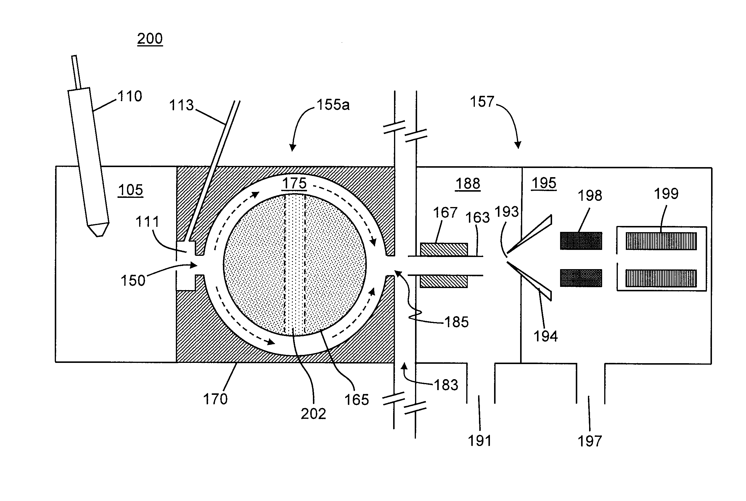
[0038]FIGS. 2A-2B are schematic diagrams depicting a system for analyzing ions including an ion mobility device in accordance with the present teachings. The system 200 (FIGS. 2A-2B) comprises several similar components, numbered similarly, to those already illustrated in and discussed in reference to FIG. 1A. However, in contrast to the system illustrated in FIG. 1A, the system 200 comprises a FAIMS cell 155a that is modified from the apparatus shown in FIG. 1A. In particular, the FAIMS 155a (FIGS. 2A-2B) has a cylindrical inner electrode 165 having a throughgoing conduit (a hole or bore) 202 that is substantially perpendicular to the cylindrical axis (note that the axis of the cylindrical inner electrode 165 is perpendicular to the plane of the drawing in FIG. 2A and other of the accompanying figures). Furthermore, the cylindrical inner electrode 165 is disposed within the FAIMS cell 155a such that it may be rotated about its axis so as to change the disposition or orientation of ...

third embodiment

[0045]FIG. 4A is a schematic diagram depicting a system for analyzing ions including an ion mobility device in accordance with the present teachings. The system 400 shown in FIG. 4A is generally similar to the system 100 (FIG. 1A) but with most of the mass spectrometer 157 not illustrated. Accordingly, FIG. 4A employs similar reference numbers for components that have already been introduced in and described in reference to FIG. 1A. As previously described, the system 400 comprises a small gap 183 separating a FAIMS cell 155 from a mass spectrometer 157. However, in contrast to the system 100, carrier gas is not allowed to vent through the gap 183. Instead, in the system 400, a reduced-diameter inlet orifice 150 and an air-tight seal 402 between the FAIMS cell 155 and the mass spectrometer 157 combine to enable the mass spectrometer vacuum system to pull a rate-restricted, pressure-reduced flow of gas through the FAIMS cell. The pressure within the FAIMS cell may thus be maintained ...

fourth embodiment

[0047]FIG. 5A is a schematic diagram depicting a system for analyzing ions including an ion mobility device in accordance with the present teachings. As in the system 400 (FIG. 4A), the system 500 (FIG. 5A) utilizes the vacuum system of the mass spectrometer 157 to maintain a reduced pressure within the FAIMS cell 155. In the system 500, the restriction of the rate of flow of carrier gas is provided by ion transfer tube 120, such as a capillary tube, that it coupled to the desolvation chamber 111 and the inlet orifice 150 of the FAIMS cell 155. A heater jacket 135 may be coupled to the ion transfer tube so as to promote de-solvation and solvent evaporation prior to ions entering the FAIMS cell. The system 510 shown in FIG. 5B is modified relative to the system 500 by replacement of the FAIMS cell 155 with the reconfigurable FAIMS cell 155a (or, alternatively, with the reconfigurable FAIMS cell 155b).

[0048]FIG. 6A is a schematic diagram depicting another embodiment of a system for an...


PUM


Abstract

A system for analyzing ions comprises: an ion source; a FAIMS cell comprising: (a) a gas inlet; (b) an outer electrode having a generally concave inner surface and comprising: (i) an ion inlet operable to receive the ions from the ion source and a carrier gas from the gas inlet; and (ii) an ion outlet; and (c) an inner electrode having a conduit therethrough and having a generally convex outer surface that is disposed in a spaced-apart and facing arrangement relative to the inner surface of the outer electrode for defining an ion separation region therebetween; and a mass analyzer for mass analyzing ions transmitted by the FAIMS cell through the ion outlet, wherein the inner electrode is moveable between a first position and a second position, the first position facilitating movement of the ions through the ion separation region, the second position facilitating movement of the ions through the conduit.

Description

FIELD OF THE INVENTION[0001]The present invention relates generally to ion spectrometry, and more particularly to coupling between an ion mobility spectrometry device, such as a high field asymmetric ion mobility spectrometry (FAIMS) cell, and a mass spectrometer.BACKGROUND OF THE INVENTION[0002]In ion mobility spectrometry devices, separation of gas-phase ions is accomplished by exploiting variations in ion drift velocities under an applied electric field arising from differences in ion mobilities. One well-known type of ion mobility spectrometry device is the High Field Asymmetric Waveform Ion Mobility Spectrometry (FAIMS) cell, also known by the term Differential Ion Mobility Spectrometry (DIMS) cell, which separates ions on the basis of a difference in the mobility of an ion at high field strength (commonly denoted as Kh) relative to the mobility of the ion at low field strength (commonly denoted as K). Briefly described, a FAIMS cell consists of a pair of spaced apart electrode...

Claims


Application Information

Patent Timeline
IPC IPC(8): H01J49/04H01J49/24H01J49/26
CPCG01N27/624
Inventor BELFORD, MICHAEL W.DUNYACH, JEAN-JACQUESHARDMAN, MARK E.
Owner THERMO FINNIGAN
Why Eureka
Try Eureka