Thermal sensors and methods of operating thereof

a technology of thermometers and sensors, applied in the field of thermometers, can solve the problems of poor temperature measurement accuracy, and thus better dac code-to-temperature linearity, and achieve the effects of improving the accuracy of the temperature sensing circuitry, simple temperature calibration, and accurate temperature sensing

Active Publication Date: 2011-10-20
TAIWAN SEMICON MFG CO LTD
View PDF29 Cites 22 Cited by
  • Summary
  • Abstract
  • Description
  • Claims
  • Application Information

AI Technical Summary

Benefits of technology

Embodiments of the application can have one or a combination of the following features and / or advantages. Embodiments of the temperature sensing circuit can be integrated in semiconductor circuitry manufactured by advanced CMOS (Complementary Metal Oxide Semiconductor) processes. The linear relationship between the temperatures and the DAC codes increases accuracy of the temperature sensing circuitry and allows simple temperature calibration that, in turn, enables accurate temperature sensing.

Problems solved by technology

This approach, however, suffers from DAC code-to-temperature non-linearity issues, i.e., it cannot achieve good linearity over a wide temperature range, resulting in poor temperature measurement accuracy.
When the compared voltage is PTAT, the implementation scheme introduces an intrinsic DAC code-to-temperature nonlinearity, and, as a result, suffers from poor temperature measurement accuracy unless an extensive temperature calibration (e.g., many-point calibration) is performed.
Other approaches trying to cause the compared (or reference) voltage family curves to be parallel, and thus better DAC code-to-temperature linearity, are far from successful because the curves, in reality, are not parallel.
These approaches therefore also suffer from poor temperature measurement accuracy.

Method used


Image

  • Thermal sensors and methods of operating thereof
  • Thermal sensors and methods of operating thereof
  • Thermal sensors and methods of operating thereof

Examples


1st embodiment

Circuit Providing VCTAT and VCMP—1st Embodiment

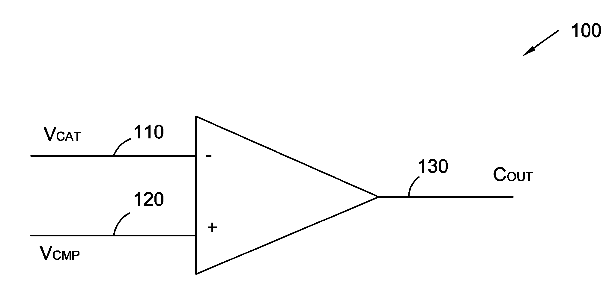
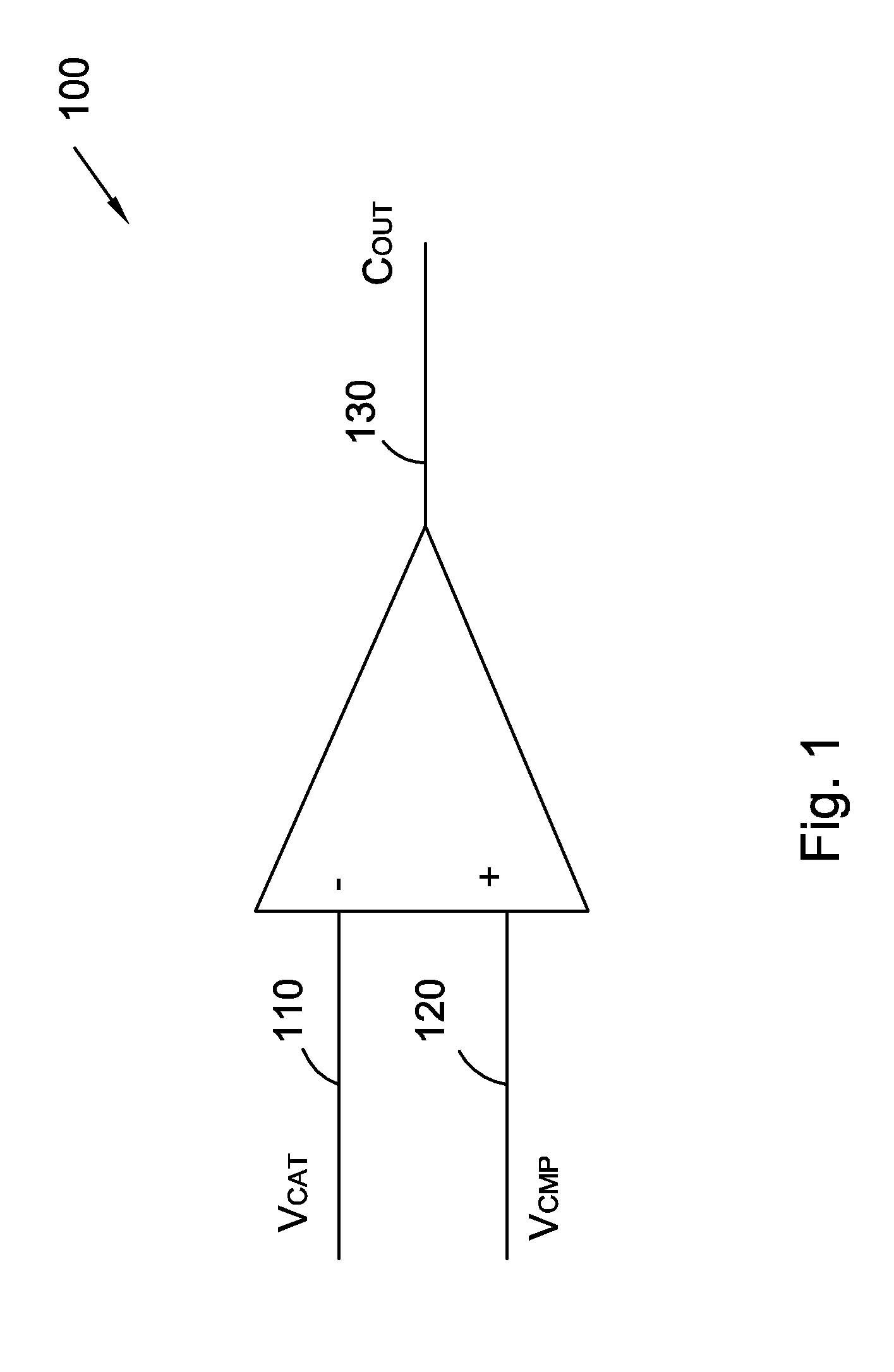
FIG. 4 shows a circuit 400 providing VCTAT and VCMP, in accordance with a first embodiment. For illustration purposes, FIG. 4 also includes comparator 100. VCMP, going through circuit 400 having a negative temperature coefficient circuit component canceling the temperature effect with a positive temperature coefficient circuit component results in a low or insignificant temperature coefficient.

Transistors M1, M2 and amplifier A1 constitute a current mirror wherein amplifier A1 equalizes currentIM1 and IM2 and voltages at NODE1 and NODE2. Because IM1 equals to IM2, IM, for illustration purposes, is used to refer to either IM1 or IM2. At node NODE1 IM1=I21+IQ1 while at node NODE2 IM2=IQ2+I22. Bipolar transistor Q1 is configured as a diode because a diode has negative temperature coefficient. VCTAT is in fact VBE (voltage from the base to emitter) of transistor Q1, and, for illustration purpose, is referred to as VBEQ1. Bipolar transistor ...


PUM

PropertyMeasurementUnit
temperatureaaaaaaaaaa

Abstract

A thermal sensor includes a comparator having a first and second input nodes. A reference voltage generator is electrically coupled with the first input node. The reference voltage generator is configured to provide a reference voltage that is substantially temperature-independent. A temperature sensing circuit is electrically coupled with the second input node. The temperature sensing circuit is configured to provide a temperature-dependent voltage. The temperature sensing circuit includes a current mirror. A first metal-oxide-semiconductor (MOS) transistor is electrically coupled between the current mirror and ground. A first resistor is electrically coupled with the current mirror. A second MOS transistor is electrically coupled with the first resistor in series. The second MOS transistor and the first resistor are electrically coupled with the first MOS transistor in a parallel fashion.

Description

TECHNICAL FIELDEmbodiments of the application are related to generating linear relationship between temperatures and digital codes. Various embodiments are used in temperature sensors.BACKGROUNDA temperature sensor can be used to monitor temperature of an electronic component such as a CPU (Central Processing Unit), CPU (Graphics Processing Unit), MPU (Micro Processing Unit), SOC (System On Chip), etc. When the temperature exceeds predetermined thresholds, the sensor may alert a circuitry to slow down or even shut down the unit to reduce power consumption and thus reduce the temperature so that overheat that can cause destructive failure to the unit may be prevented.Typically, temperature sensors include a reference circuitry and a temperature measuring circuitry wherein the temperature dependency is either proportional to absolute temperature (PTAT) or complementary to absolute temperature (CTAT). Further, DAC (digital to analog converter) based temperature sensors relying on compa...

Claims


Application Information

Patent Timeline
Patent Type & Authority Applications(United States)
IPC IPC(8): G01K7/02
CPCG01K2219/00G01K7/01
Inventor SWEI, STEVEN
Owner TAIWAN SEMICON MFG CO LTD
Why Eureka
Try Eureka