

Fluid flow control device for an aerofoil
- Summary
- Abstract
- Description
- Claims
- Application Information
AI Technical Summary
Benefits of technology
Problems solved by technology
Method used
Image

Examples
first embodiment
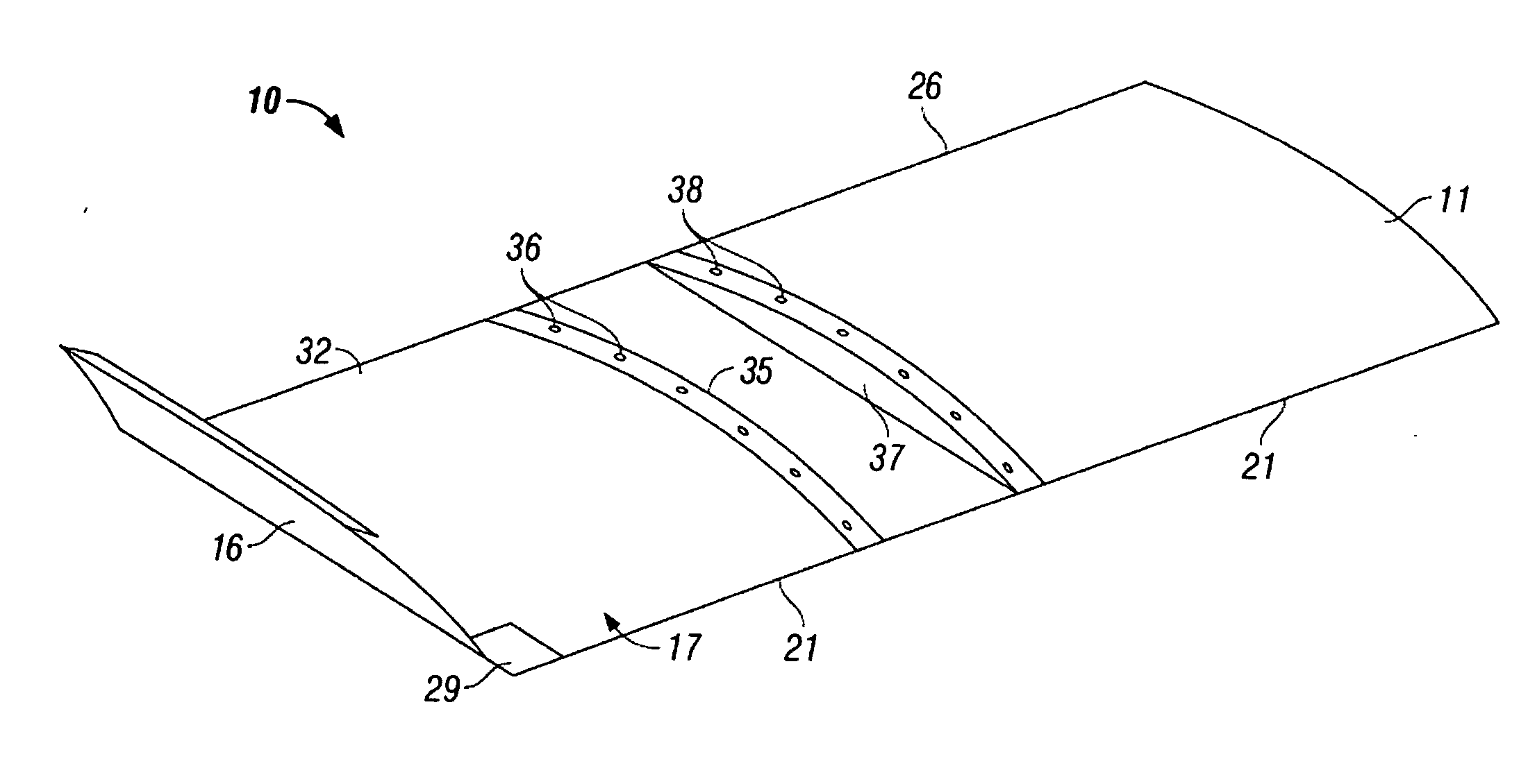
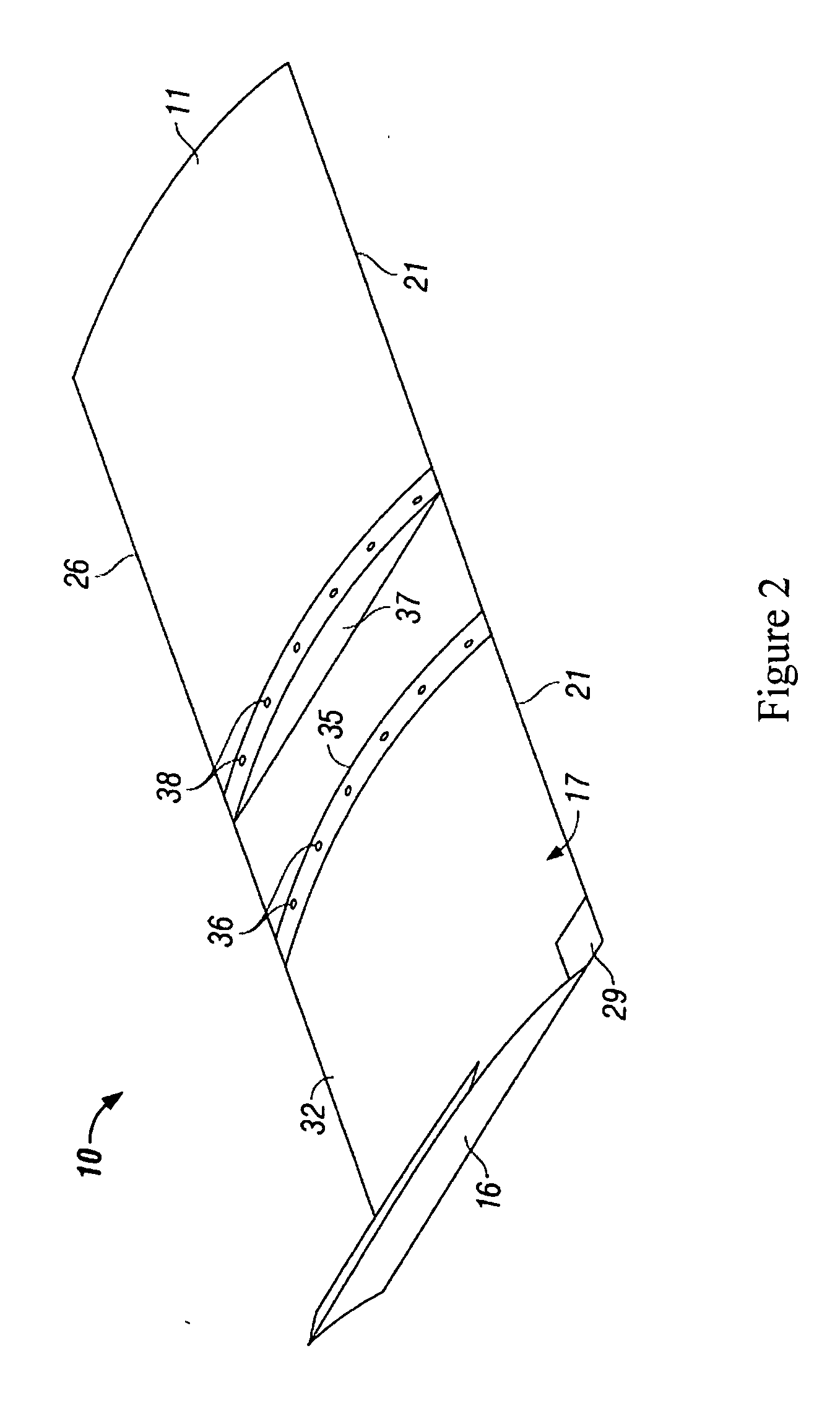
[0059]Referring to FIGS. 2 to 7, the invention provides a fluid flow control device 10 for an aerofoil 11 comprising an aerofoil-tip body 17, coupling apparatus 36, 38 and a passive tip blowing assembly 16.
[0060]The aerofoil-tip body 17 is of aerofoil shape having a low pressure side 32 and a high pressure side 33. The coupling apparatus 36, 38 is adapted to couple one end 35 of the aerofoil-tip body 17 to a distal end 37 of an aerofoil 11.
[0061]The passive tip blowing assembly 16 is provided at the other end of the aerofoil-tip body 17. The assembly 16 comprises a housing 18 defining a fluid chamber 23 and a vane 22 of aerofoil shape provided within the fluid chamber. The fluid chamber 23 extends along part of the chord-length of the aerofoil-tip body 17 and has a fluid inlet 27 at the high pressure side 33 and a fluid outlet 28 at the low pressure side 32. The vane 22 is arranged along the chord of the aerofoil-tip body, within the fluid chamber 23, with its leading edge 22a gener...
third embodiment
[0083]Referring to FIG. 11, the invention provides an aerofoil 40 comprising a body 42 having a leading edge 42a and a trailing edge 42b. A fluid flow control device 17 as described in FIGS. 1 to 7 is provided at the distal end 44 of the aerofoil body 42. The same reference numbers are retained for corresponding features.
fourth embodiment
[0084]the invention provides an aircraft wing 50, as shown in FIG. 12. The aircraft wing 50 comprises a root portion 52 for connection to the body of an aircraft (not shown), a central portion 54 comprising the main span of the wing 50, and a distal end portion 56. The central portion 54 has a leading edge 54a and a trailing edge 54b. A fluid flow control device 17 as described in FIGS. 1 to 7 is provided at the distal end of the distal end portion 56. The same reference numbers are retained for corresponding features.
PUM
 Abstract
Description
Claims
Application Information