Coil-type electronic component and its manufacturing method

a manufacturing method and electronic component technology, applied in the direction of solid-state diffusion coating, magnetic bodies, inductances, etc., can solve the problems of low insulation property of metal magnetic materials themselves, inability to support further size reduction, and increased production costs, so as to achieve high saturation magnetic flux density, low cost, and high magnetic permeability

Active Publication Date: 2011-11-03
TAIYO YUDEN KK
View PDF3 Cites 75 Cited by
  • Summary
  • Abstract
  • Description
  • Claims
  • Application Information

AI Technical Summary

Benefits of technology

[0012]The present invention was developed in light of the aforementioned situations and provides a coil-type electronic component equipped with a magnetic material that

Problems solved by technology

On the other hand, metal magnetic materials themselves have low insulation property and must be given insulation treatment.
This material also presents a problem in that it does not support further size reduction if applied to power inductors or other electronic components through which gre

Method used


Image

  • Coil-type electronic component and its manufacturing method
  • Coil-type electronic component and its manufacturing method
  • Coil-type electronic component and its manufacturing method

Examples


example 1

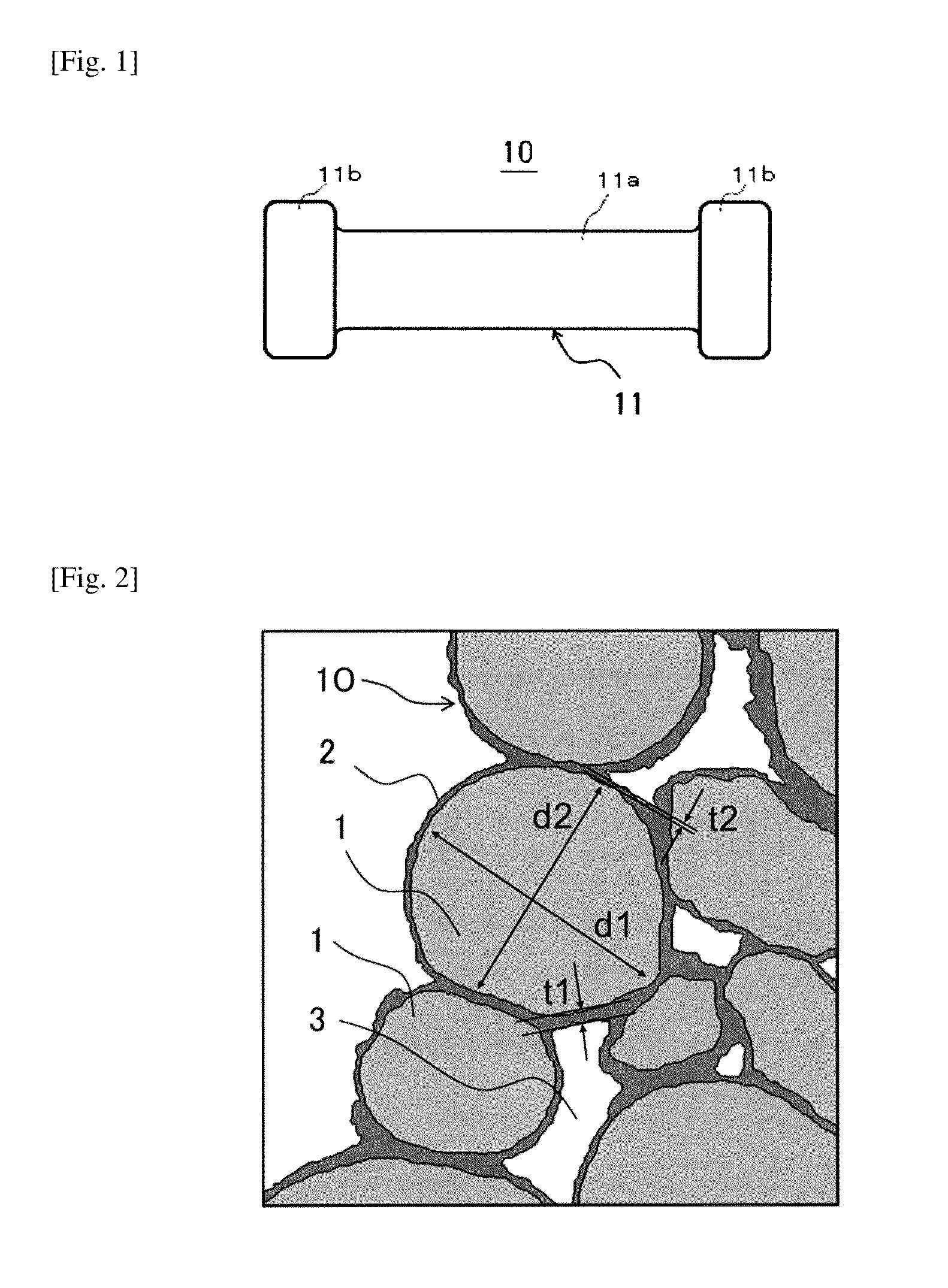
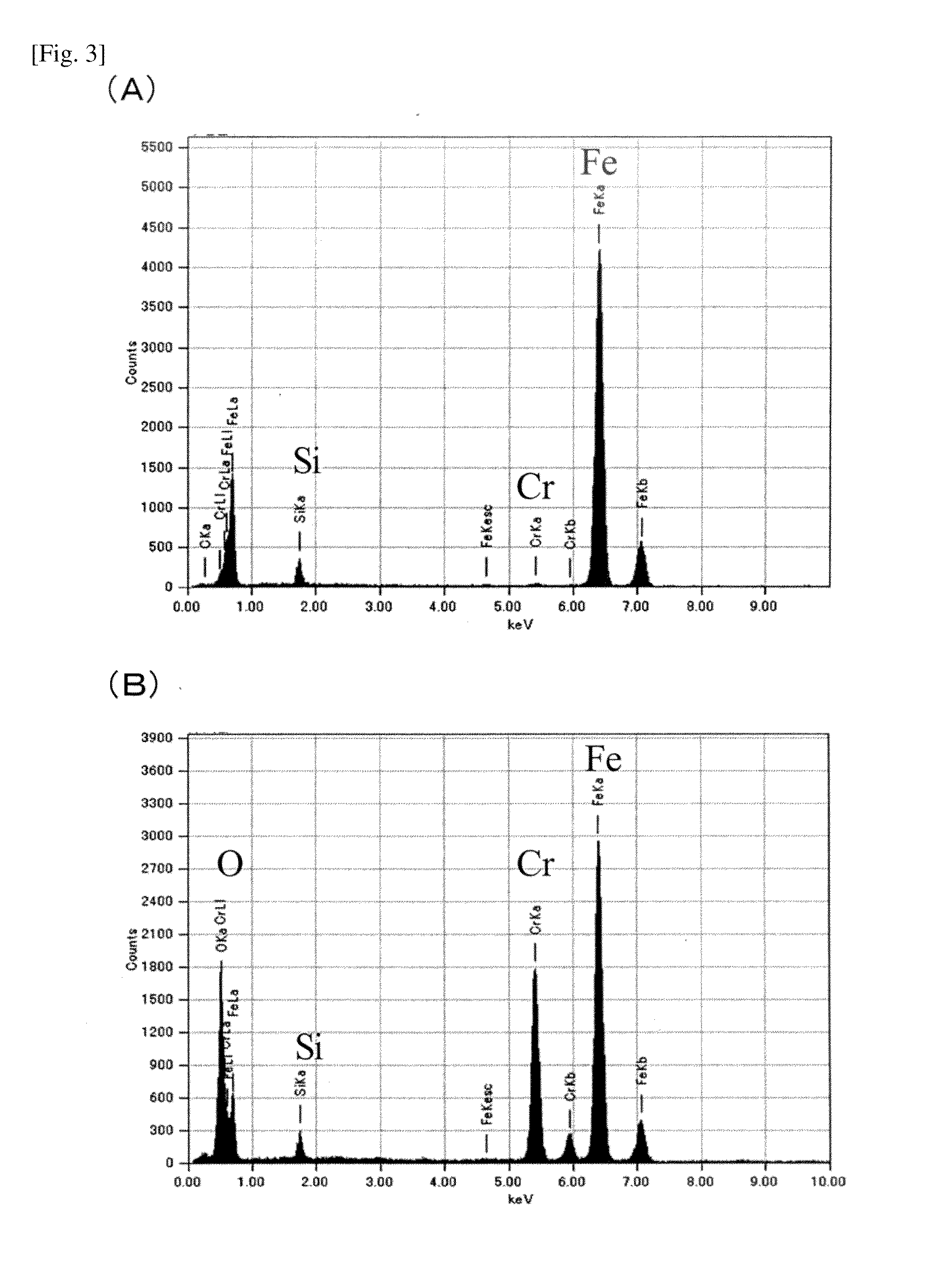
[0187]For the material grains to obtain a base material using a soft magnetic alloy for an electronic component, alloy powder (PF-20F manufactured by Epson Atmix) was used which is a type of water-atomized powder whose average grain size (d50%) is 10μ and composition ratio was 5 percent by weight of chromium, 3 percent by weight of silicon and 92 percent by weight of iron. The average grain size d50% of material grains described above was measured using a granularity analyzer (9320HRA manufactured by Nikkiso). Each of the above grains was polished until its cross-section in a thickness direction cutting across roughly the center of the grain was exposed, and the obtained cross-section was captured with a scanning electron microscope (SEM: S-4300SE / N manufactured by Hitachi High-Technologies) at a magnification of 3000 times to obtain a composition image, which was then used to calculate the composition of 1 μm2 near the center of the grain and also near the surface by the ZAF method...

example 2

[0203]Evaluation samples were created in the same manner as in Example 1, except that the composition ratio of material grains was changed to 3 percent by weight of chromium, 5 percent by weight of silicon and 92 percent by weight of iron. The obtained results are shown in Tables 1 and 2.

[0204]As shown in Tables 1 and 2, all of the results of measurement and judgment were favorable, as in Example 1, with the magnetic characteristics being 1.46 T in saturation magnetic flux density Bs and 43 in magnetic permeability μ, strength of the base material being 2.8 kgf / mm2, volume resistivity being 2.0×10⁵ Ωcm, and formability of metal plating layer being ◯. SEM-EDS analysis confirmed that the grains were bonded with one another via the metal oxide (oxide layer) formed on the surfaces of the grains by the heat treatment, and the oxide layer was an oxide containing an element that oxidizes more easily than iron (here chromium) by a quantity larger than that in the alloy grains.

example 3

[0205]Evaluation samples were created in the same manner as in Example 1, except that the average grain size (d50%) of material grains was changed to 6 μm. The obtained results are shown in Tables 1 and 2.

[0206]As shown in Tables 1 and 2, all of the results of measurement and judgment were favorable, as in Example 1, with the magnetic characteristics being 1.45 T in saturation magnetic flux density Bs and 27 in magnetic permeability strength of the base material being 6.6 kgf / mm2, volume resistivity being 3.0×10⁵ Ωcm, and formability of metal plating layer being ◯. SEM-EDS analysis confirmed that the grains were bonded with one another via the metal oxide (oxide layer) formed on the surfaces of the grains by the heat treatment, and the oxide layer was an oxide containing an element that oxidizes more easily than iron (here chromium) by a quantity larger than that in the alloy grains.


PUM

PropertyMeasurementUnit
Percent by massaaaaaaaaaa

Abstract

A coil-type electronic component has a coil inside or on the surface of its base material and is characterized in that: the base material is constituted by a group of grains of a soft magnetic alloy containing iron, silicon and other element that oxidizes more easily than iron; the surface of each soft magnetic alloy grain has an oxide layer formed on its surface as a result of oxidization of the grain; this oxide layer contains the other element that oxidizes more easily than iron by a quantity larger than that in the soft magnetic alloy grain; and grains are bonded with one another via this oxide layer.

Description

BACKGROUND[0001]1. Field of the Invention[0002]The present invention relates to a coil-type electronic component and its manufacturing method. In particular, the present invention relates to a coil-type electronic component using a soft magnetic alloy suitable for coil-type electronic components that are made small enough to be mounted on the surfaces of circuit boards, as well as a manufacturing method for said coil-type electronic component.[0003]2. Description of the Related Art[0004]Traditionally ferrite cores, cores cut out from thin metal sheets, and compacted powder magnetic cores, are used as magnetic cores for choke coils subject to high frequencies.[0005]Metal magnetic materials provide an advantage over ferrite in that they can achieve higher saturation magnetic flux densities. On the other hand, metal magnetic materials themselves have low insulation property and must be given insulation treatment.[0006]Patent Literature 1 (Japanese Patent Laid-open No. 2001-11563) propo...

Claims


Application Information

Patent Timeline
IPC IPC(8): H01F17/04C23C8/10
CPCB22F2998/00Y10T29/49073C22C2202/02H01F1/14766H01F1/24H01F1/33H01F41/0246C22C1/02Y10T29/49144H01F41/02H01F5/06H01F5/02H01F1/26H01F1/22H01F1/12H01F41/10H01F41/0687H01F41/125Y10T29/49071Y10T29/49069Y10T29/4902C22C33/0278H01F41/098H01F17/04H01F1/147H01F27/29
Inventor OGAWA, HIDEKITANADA, ATSUSHIMATSUURA, HITOSHITANAKA, KIYOSHIKISHI, HIROSHIKAWANO, KENJI
Owner TAIYO YUDEN KK
Why Eureka
Try Eureka