Method for producing overlapping weld joints and overlapping weld joint

Active Publication Date: 2011-11-03
AIRBUS OPERATIONS GMBH
View PDF4 Cites 7 Cited by
  • Summary
  • Abstract
  • Description
  • Claims
  • Application Information

AI Technical Summary

Benefits of technology

[0008]Therefore, the object of the present invention is to provide a method for the production of overlapping weld joints and an overlapping weld joint which overcomes the mentioned disadvantages. The method according to the invention for the production of overlapping weld joints is to make it possible to produce overlapping weld joints with a high strength and a low susceptibility to corrosion. A further object of the present invention is to be able to produce overlapping weld joints which do not have any gaps outside the actual weld in which moisture or other media can be trapped.
[0013]Thereafter, the non-welded regions of the overlapping component material are removed in the overlap region, thereby forming outer cut surfaces on the components which are arranged at an obtuse angle to the overlap region. As described above, when the components are welded in the overlap region of the bases, non-welded regions in which the components rest against one another or form a gap remain next to the weld. In order to remove these regions, which are susceptible to corrosion since moisture can also collect here by capillary action, the non-welded material next to the weld is removed. In this respect, the bases advantageously allow the material to be removed, without the base material outside the bases being damaged during said removal.
[0014]According to a preferred development of the present invention, at least two substantially parallel welds are formed when the two components are welded. The provision of a plurality of welds running next to one another can provide an increased strength when the two components are joined. The individual welds are preferably arranged next to one another without a gap. In so doing, the individual welds more preferably overlap one another. This prevents moisture from penetrating between the individual adjacent welds and being able to cause corrosion there.
[0015]More preferably, in the method according to the invention for the production of overlapping weld joints, friction-stir welding is used as the welding method, in which a rotating welding tool is pressed against at least one of the components to generate friction heat. In the first step of this welding method, a rotating tool is preferably pressed with sufficiently high force into the joint gap between the two components until a shoulder of the tool rests against the upper surface of the component. During the second step, the rotating tool remains for a few seconds at the immersion point. Due to the friction between the tool shoulder and the joint partners, the tool heats up under the shoulder to just below melting point. The result of this rise in temperature is a reduction in solidity, and consequently the material is plasticised and a blending of the joint zone is possible. The commencement of the forwards movement indicates the start of the third step in which the rotating tool is moved along the joint line with a high contact pressure force. The pressure gradient, resulting from the forwards movement, between the front and back of the tool and the rotational movement thereof induce the transport of plasticised material around the tool, where the material is mixed and forms the weld. At the end of the weld, the tool is removed from the joint zone. The advantages of friction-stir welding are that no additional tools are required, high weld strengths can be achieved, an inert gas is not required, the process sequence is relatively simple, a broad spectrum of mix connections can be realised and welding can be carried out at relatively low process temperatures, thereby producing a low distortion and the structural characteristics of the components to be welded are only slightly affected.
[0017]According to a preferred embodiment, the auxiliary tool is at least partly provided with a scratch-proof, anti-adhesive coating. More preferably, a Teflon coating or preferably a ceramic coating is provided for this purpose. This has the advantage that the heated welded material does not adhere to the auxiliary tool or damage it.

Problems solved by technology

If lap joints are joined together by spot welding, friction-stir welding or other welding methods which do not provide fillet joints along the edges, the problem arises that joining gaps are produced outside the welded areas between the components which are joined together.
These gaps are susceptible to corrosion because, among other reasons, moisture can become trapped here.
It is difficult to completely fill the narrow gaps with an anti-corrosive coating.
For this reason, the durability of this type of overlapping weld joint is not optimum.
However, these fillers react to some extent with the material in the weld zone at the high processing temperatures and alter the material characteristics during the welding process.

Method used


Image

  • Method for producing overlapping weld joints and overlapping weld joint
  • Method for producing overlapping weld joints and overlapping weld joint
  • Method for producing overlapping weld joints and overlapping weld joint

Examples


first embodiment

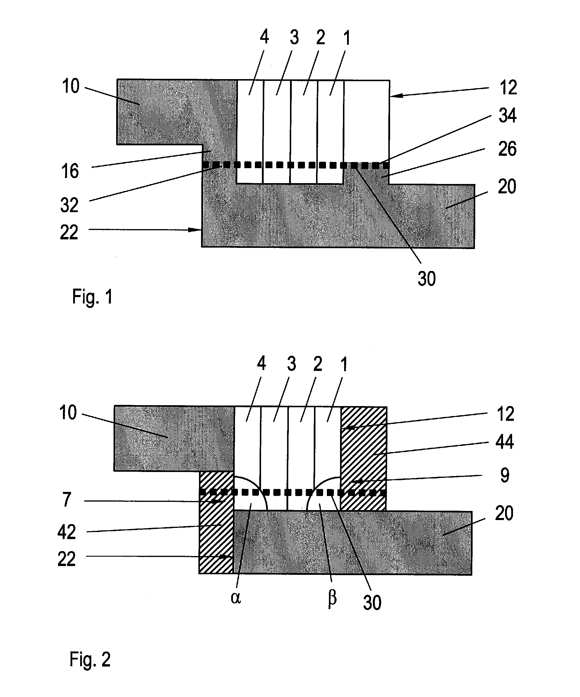
[0025]FIG. 1 is a schematic sectional view of an overlapping weld joint of the invention in a first production stage. The sectional view has been chosen such that friction-stir welds 1, 2, 3, 4 extend into the plane of the paper along a first component 10 and a second component 20 to be joined thereto. The first component 10 has a base-shaped elevation 16 which is shown here on the lower side of the component 10. The second component 20 also has a base-shaped elevation 26 which is shown here on the upper side of the second component 20. The components 10, 20 overlap with the bases 16, 26 in an overlap region 30 which is shown here as a dotted line. In this view, four friction-stir welds 1, 2, 3, 4 are made next to one another in the second component 20 downwards from above through the first component 10. The friction-stir welds 1, 2, 3, 4 adjoin one another, overlapping each other at the sides and, in this view, extend substantially vertically to the plane of the paper. Provided in...

second embodiment

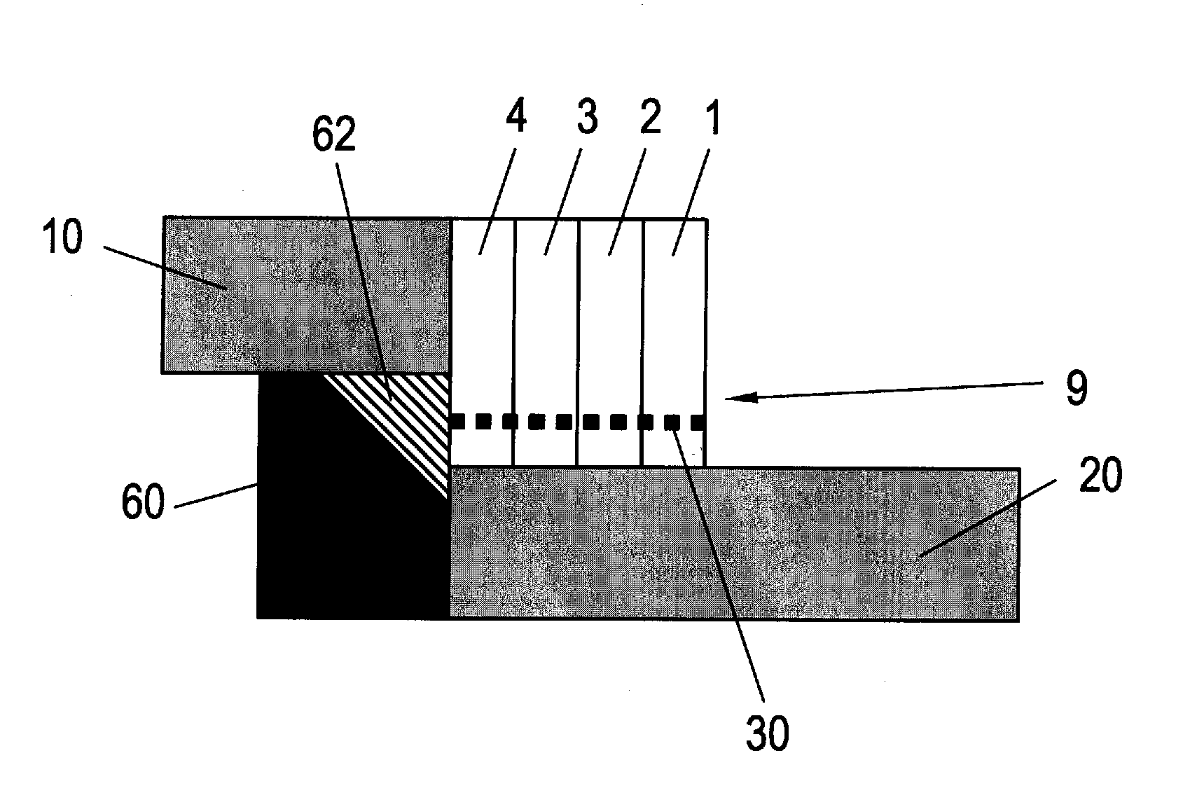
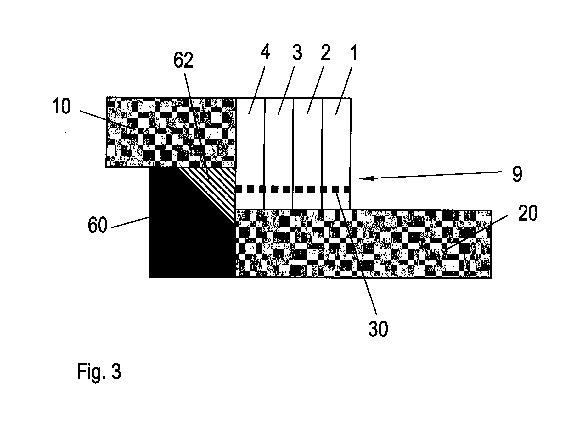
[0028]FIG. 3 is a schematic sectional view of an overlapping weld joint of the invention according to a Two overlapping components 10, 20 which are constructed analogously to the components in FIGS. 1 and 2 are welded together by four stir friction welds 1, 2, 3, 4. In the right-hand region of the illustration, the overlap region 30 has been removed up to the weld 1 by a subsequent machining operation corresponding to the embodiment of FIG. 2 in order to produce a gap-free join. The left-hand region of the illustration shows an auxiliary tool 60 which has a recess 62 on the upper right-hand side. The auxiliary tool is arranged such that the component 10 is clamped between the auxiliary tool 60 and the welding tool 50 and both components 10, 20 rest against the auxiliary tool 60. Material from both components 10, 20 is pressed into a recess 62 in the auxiliary tool 60 which adjoins both components 16, 26.

[0029]As a result, a gap-free welded joint 1 is produced according to this embo...


PUM

PropertyMeasurementUnit
Angleaaaaaaaaaa
Frictionaaaaaaaaaa

Abstract

A method for manufacturing welded lap joints comprising the following steps: Providing of two components each having at least one base; allocating the components in such a way that the bases face each other and the components overlap in an overlapping area, which extends at least partially over both components; joining the components by welding in the overlapping area such that a weld joint is formed, wherein at the edge of the overlapping area non welded areas are formed; removing of the non welded areas whereby outer cutting areas are formed at the components, which are arranged at obtuse angles to the overlapping area.

Description

CROSS-REFERENCE TO RELATED APPLICATIONS[0001]This application is a continuation of and claims priority to PCT International Application No. PCT / EP2009 / 065505 filed Nov. 19, 2009, which claims the benefit of and priority to U.S. Provisional Application No. 61 / 118,255, filed Nov. 26, 2008 and German Patent Application No. 10 2008 044 087.6, filed Nov. 26, 2008, the entire disclosures of which are herein incorporated by reference.FIELD OF THE INVENTION[0002]The present invention relates to a method for the production of overlapping weld joints and to an overlapping weld joint of this type.[0003]The term “welding” (according to DIN standard DIN EN 14610 and DIN 1910-100) is understood as meaning the unreleasable joining of components using heat or pressure, with or without additional welding materials. Depending on the welding method, the join is made in a welding seam or in a welding spot, and also in a surface in the case of friction welding. The energy required for welding is supplie...

Claims


Application Information

Patent Timeline
IPC IPC(8): F16B11/00B32B37/00B29C65/06B23K20/12B23K31/02B32B38/10
CPCB23K37/06B23K20/1265Y10T156/10Y10T403/477Y10T156/108
Inventor PACCHIONE, MARCOSILVANUS, JUERGEN
Owner AIRBUS OPERATIONS GMBH
Why Eureka
Try Eureka