Method and System For Enhancing A Recovery Process Employing One or More Horizontal Wellbores

a recovery process and wellbore technology, applied in the direction of fluid removal, earth drilling and mining, borehole/well accessories, etc., can solve the problems of limiting production rate and resource recovery, affecting the recovery process, so as to enhance the recovery process and facilitate the movement of flowable materials , the effect of increasing permeability

Inactive Publication Date: 2011-11-10
EXXONMOBIL UPSTREAM RES CO
View PDF3 Cites 25 Cited by
  • Summary
  • Abstract
  • Description
  • Claims
  • Application Information

AI Technical Summary

Benefits of technology

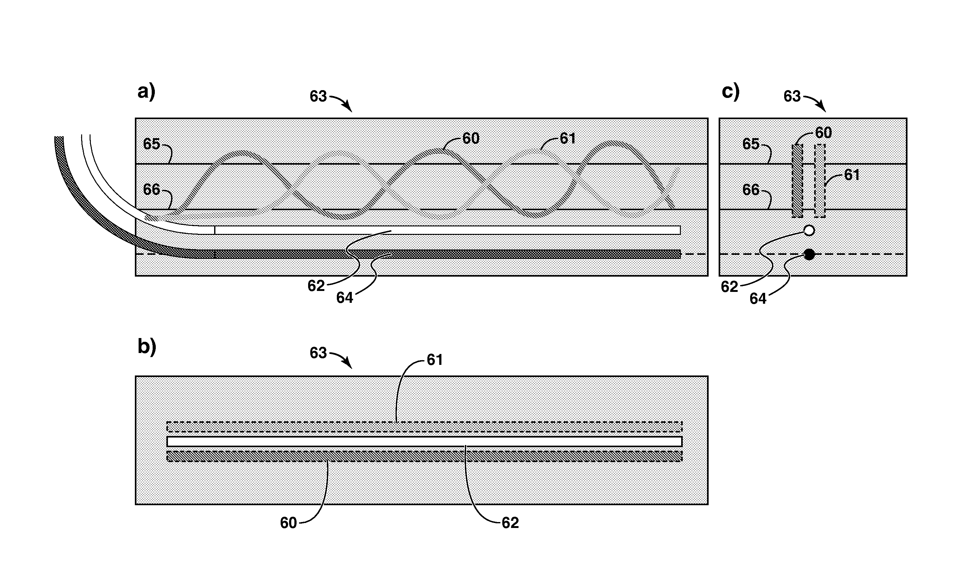
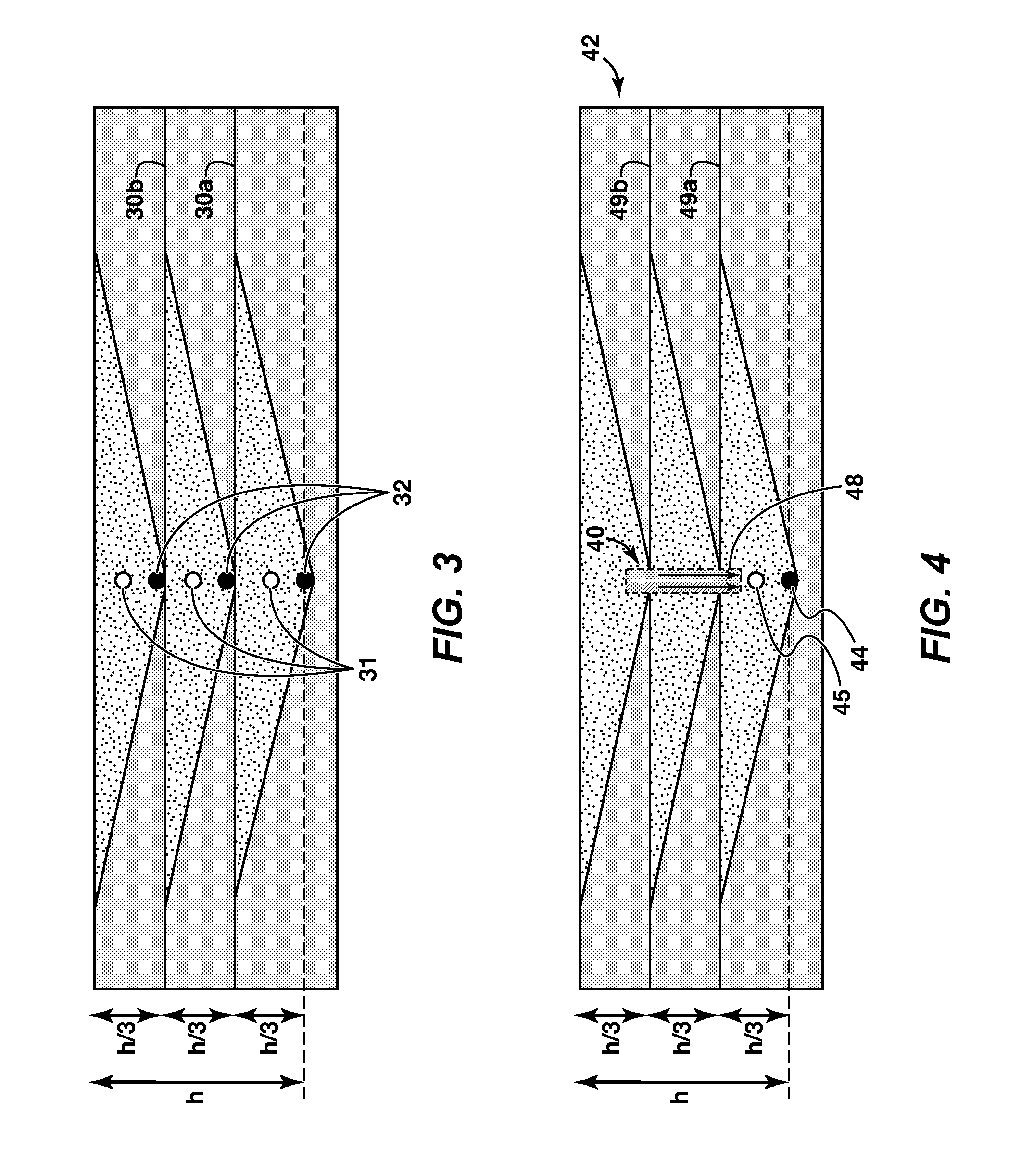
In another aspect, there is provided method of increasing permeability of at least one vertical permeability impediment in a reservoir to enhance a hydrocarbon recovery process employing one or more horizontal wellbores. The method comprises providing at least one accessory conduit in the reservoir in a region substantially above or below the one or more horizontal wellbores. The conduit has one or more portions that extend through the at least one vertical permeability impediment to facilitate movement of flowable material therethrough to enhance the recovery process.
In another aspect, there is provided a method of enhancing a hydrocarbon recovery process employing one or more horizontal wellbores in a reservoir having at least one vertical permeability impediment. The method comprises increasing the effective permeability of the at least one vertical permeability impediment in a region substantially above or below the one or more horizontal wellbores to facilitate the movement of flowable materials through the at least one vertical permeability impediment to enhance the recovery process.
In another aspect, there is provided a method of enhancing recovery process performance in a hydrocarbon reservoir having at least one vertical permeability impediment. The method comprises providing a first wellbore having a substantially horizontal portion for collection of hydrocarbons. The method further comprises providing at least one accessory conduit extending through the reservoir in a region substantially above or below the first wellbore. The accessory conduit has one or more portions that extend through the vertical permeability impediment to facilitate movement of flowable materials therethrough to enhance recovery.
In another aspect, there is provided an in situ heavy oil recovery process for recovering hydrocarbons from a reservoir having one or more vertical permeability impediments. The method comprised providing one or more horizontal wellbores in the reservoir, including a production wellbore, and increasing the effective permeability of the one or more vertical permeability impediments above the production wellbore in a region extending along at least a portion of the length of the production wellbore to facilitate the movement of flowable materials through the one or more vertical permeability impediments and toward the production wellbore.
In yet another aspect, there is provided a system for recovering hydrocarbons from a reservoir. The system comprises one or more substantially horizontal wellbores, including a production wellbore, and at least one accessory conduit located substantially above or below the one or more substantially horizontal wellbores for enhancing movement of flowable materials through the reservoir to thereby enhance recovery. In some embodiments, the reservoir has at least one vertical permeability impediment and the accessory conduit has one or more portions that extend through the at least one vertical permeability impediment to facilitate movement of flowable materials therethrough.

Problems solved by technology

In-situ heavy oil recovery methods are typically applied when a deposit cannot be mined economically due to the depth of overburden.
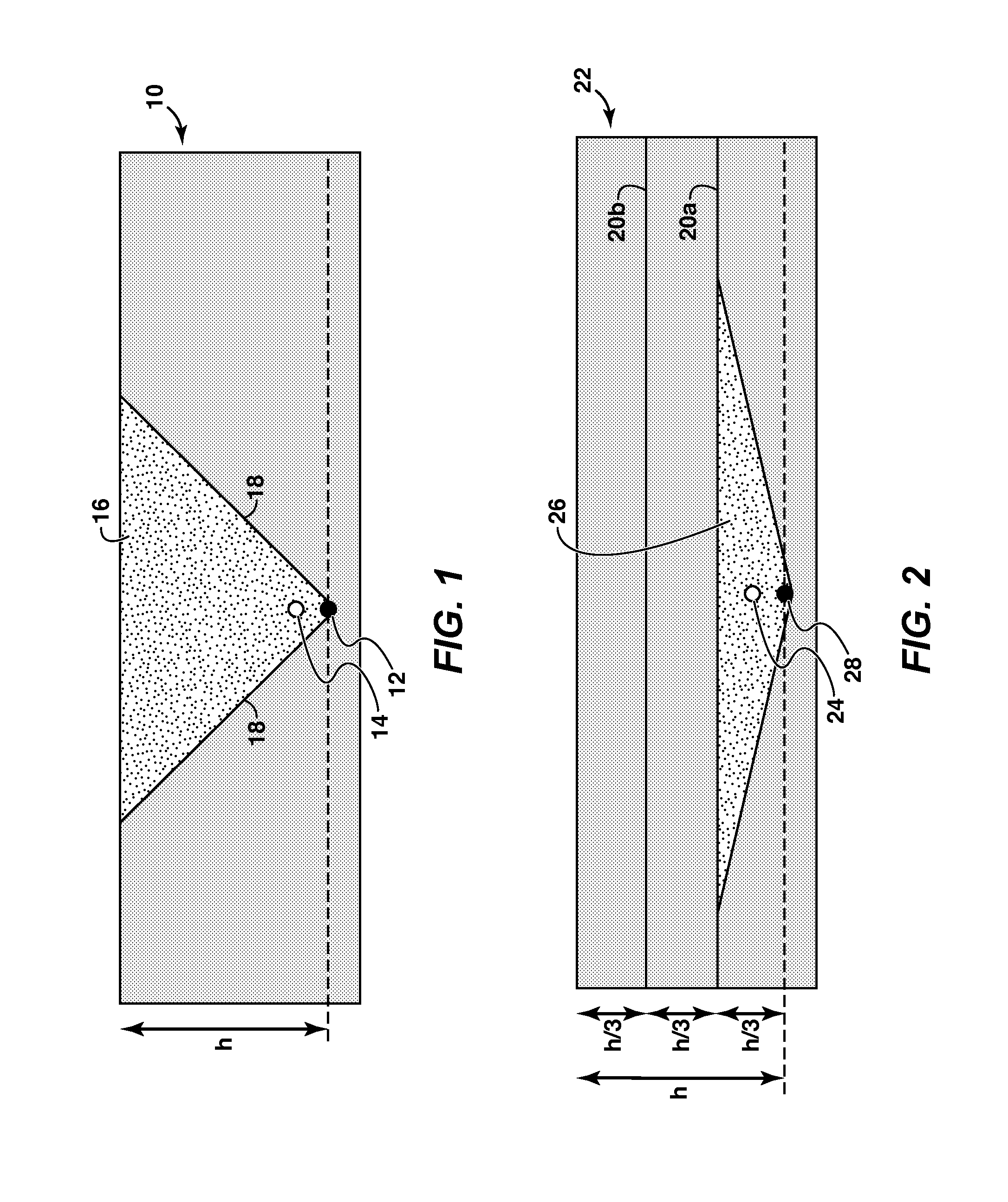
A key challenge with the practical application of any recovery process utilizing one or more horizontal wellbores, or otherwise relying on vertical movement of flowable material through a reservoir, is that permeability in most reservoirs is not homogeneous.
While the permeability of oil sand may generally be in the range of a few darcies to a few hundred darcies, the vertical permeability of an oil sands reservoir is frequently disrupted by layers of material having substantially reduced permeability.
These layers or matrices can form vertical permeability impediments that inhibit or prevent the vertical flow of materials through the reservoir, relative to the more permeable pay zones, and thus limit production rate and resource recovery.
However, each suffer from disadvantages that will be apparent to persons skilled in the art.
However, attempts to propagate fractures through compartmentalized or stratified formations have historically yielded unpredictable and poor results, such as insufficient fracture extension and inadequate propping of fractures adjacent to less permeable areas of the formation.
Such a system is not designed for gravity drainage and is not suited for reservoirs where fracture extension occurs in a horizontal versus a vertical orientation.
Moreover, a thick or substantially impermeable impediment, such as shale, may not be effectively propped open.
Such a system for increasing vertical permeability in a reservoir is costly and inefficient.

Method used


Image

  • Method and System For Enhancing A Recovery Process Employing One or More Horizontal Wellbores
  • Method and System For Enhancing A Recovery Process Employing One or More Horizontal Wellbores
  • Method and System For Enhancing A Recovery Process Employing One or More Horizontal Wellbores

Examples


example 1

Heavy Oil Reservoir Simulations Using SAGD

The time and cost involved in conducting field testing is often prohibitive in the oil and gas industry. Therefore, reservoir simulations are commonly relied upon to test new systems and processes before or while field testing is performed. In the present examples, testing was conducted using proprietary reservoir simulation software, which utilizes numerical modeling to mimic fluid flow through porous reservoir media. Reservoirs were modeled using average properties for an Athabasca oil sands deposit.

FIG. 15 shows the 2D results of a reservoir simulation modeling a typical SAGD process in a continuous oil sands reservoir with Athabasca type properties and no vertical permeability impediments. Temperature and gas saturation in the reservoir are shown for 1000 days and 2000 days of steam injection. The injection and production wells are located near the bottom left corner of each block but are not shown. The results illustrate the development...

example 2

Heavy Oil Reservoir Simulation of Split Pay Reservoir Using CSS

A numerical simulation study was conducted to evaluate applicability of the invention to cyclic steam stimulation (CSS) with horizontal wellbores. CSS is typically a single well recovery process where the same well receives a fixed volume of steam and is then produced following injection in a cyclic manner. Horizontal wells are increasingly being used to reduce the cost of field development. The horizontal wells are typically located at the base of the effective pay zone and therefore oil recovery is vulnerable to vertical permeability impediments.

A simulation model based on typical properties of the Cold Lake Clearwater formation was constructed. Referring to FIG. 18, the simulation was designed to mimic two adjacent horizontal wells (white) completed with spaced limited entry perforations (LEP), as discussed in SPE Paper 50429, “Targeted Steam Injection Using Horizontal Wells with Limited Entry Perforations”, T. Boone,...


PUM


Abstract

The present invention relates generally to a system and method for enhancing a recovery process employing one or more substantially horizontal wellbores. More particularly, the present invention relates to a method and system for enhancing a recovery process employing one or more horizontal wellbores by providing a zone of increased permeability in a hydrocarbon reservoir to facilitate vertical movement of flowable materials through the reservoir to thereby enhance the recovery process. In some embodiments, the reservoir comprises one or more vertical permeability impediments.

Description

CROSS-REFERENCE TO RELATED APPLICATIONThis application claims priority from Canadian Patent Application 2,651,527 filed Jan. 29, 2009 entitled METHOD AND SYSTEM FOR ENHANCING A RECOVERY PROCESS EMPLOYING ONE OR MORE HORIZONTAL WELLBORES, the entirety of which is incorporated by reference herein.FIELD OF THE INVENTIONThe present invention relates generally to a system and method for enhancing a hydrocarbon recovery process. More particularly, the present invention relates to a system and method for enhancing a recovery process employing one or more horizontal wellbores by selectively altering vertical permeability in a reservoir.BACKGROUND OF THE INVENTIONOil and gas are nonrenewable natural resources relied upon heavily in the industrialized world. The rising demand for oil and gas, combined with declining conventional resources, has necessitated the development of alternative sources of oil, as well as methods of enhancing recovery from both conventional and alternative resources.T...

Claims


Application Information

Patent Timeline
Patent Type & Authority Applications(United States)
IPC IPC(8): E21B43/00E21B43/12
CPCE21B43/26E21B43/2406
Inventor BOONE, THOMAS J.KOSIK, IVAN J.
Owner EXXONMOBIL UPSTREAM RES CO
Why Eureka
Try Eureka