
Method and apparatus for in-feeding of matter to a process reactor

Active Publication Date: 2011-11-10
BIO GASOL IPR APS
View PDF7 Cites 28 Cited by
  • Summary
  • Abstract
  • Description
  • Claims
  • Application Information

AI Technical Summary

Benefits of technology

[0014]It is a further object of the present invention to provide an advantageous alternative to the prior art by providing an in-feed apparatus in which in-feeding is carried out in a continuous mode.
[0069]The presence of a valve allows for control of the pressure inside the apparatus. Pressurization of the biomass inside the apparatus may be also partially provided by the dewatering means through the formation of, for example, a bio-plug. Therefore the dewatering process may contribute to the pressurization of the biomass to be fed into the reactor.

Problems solved by technology

Therefore, the skilled person is often faced with the problem of pressurising the slurry or pulp containing the biological matter so that the temperature can be increased to temperatures above the boiling temperature of the liquid while maintaining the fluid in a liquid state.
This is prone to trick safety risk and other issues relating thereto as the elevated pressure in the reactor will tend to force material upstream in the apparatus and in some cases a so-called back flash of very hot steam, ammonia, or in general chemicals and other gaseous mixtures out of the reactor and upstream in the bio-ethanol production system may occur.
Such back flash may result in e.g. breakdown and destruction of the system and in some cases cause danger to humans operating the system.
Thus there is a problem related to the prevention of back flash from occurring while allowing in-feed of biological material into the reactor.
In a further aspect, an efficient production system may require that the process in the reactor is carried continuously and in such aspects, there is a further problem relating to the in-feed needs to be continuous.
This approach has turned out not to remedy the problem and requires a needy greedy control in combination of the water content, type, comminution, amount, particle size and distribution of the biomass introduced and in-feed velocity to obtain the plug.
Naturally, the constitution of the raw material varies within broad limits and the end result is that safety issue has not been solved and the process is not very effective due to the produced plug does not always produce a tight seal.

Method used


Image

  • Method and apparatus for in-feeding of matter to a process reactor
  • Method and apparatus for in-feeding of matter to a process reactor
  • Method and apparatus for in-feeding of matter to a process reactor

Examples


Embodiment Construction

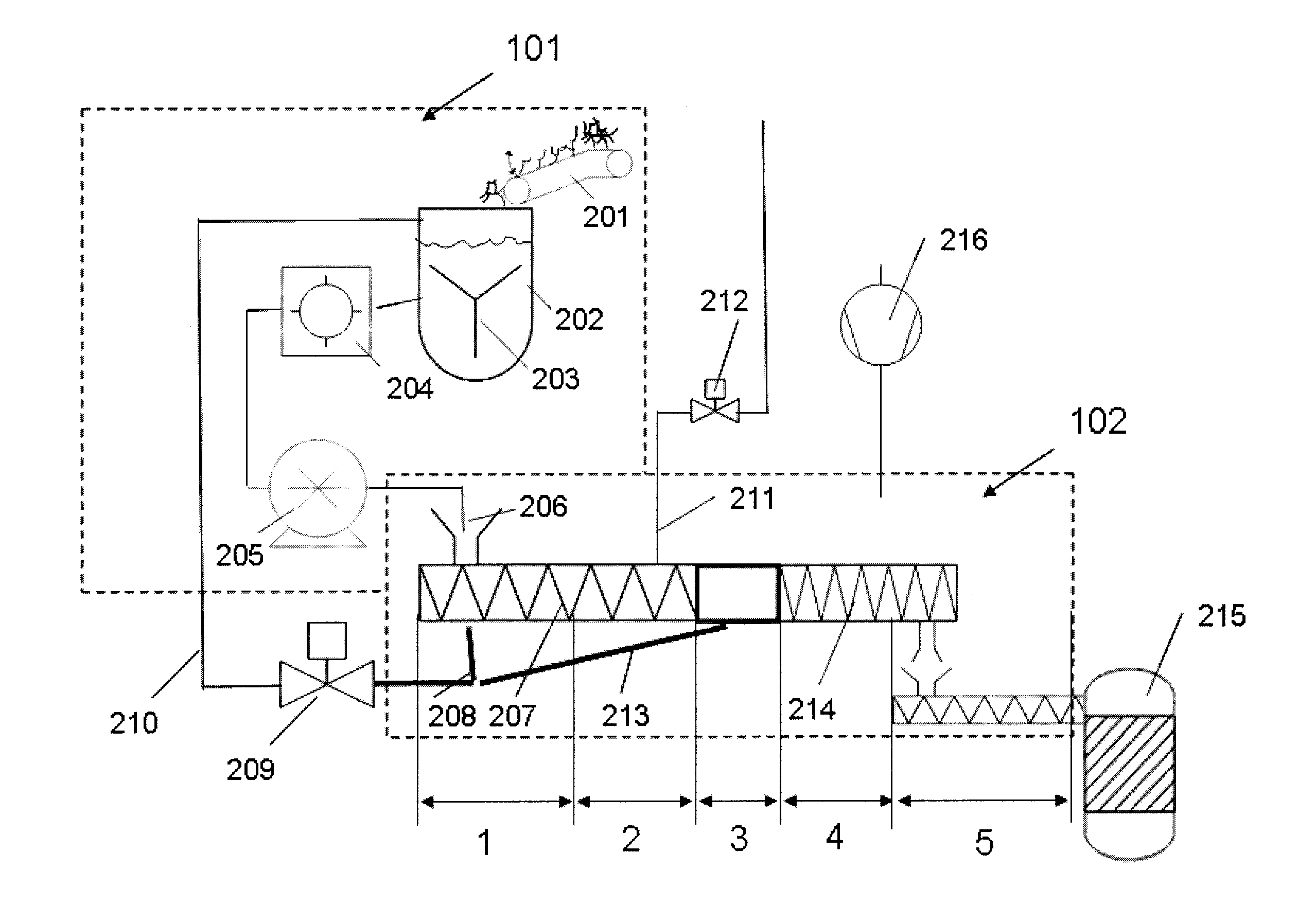
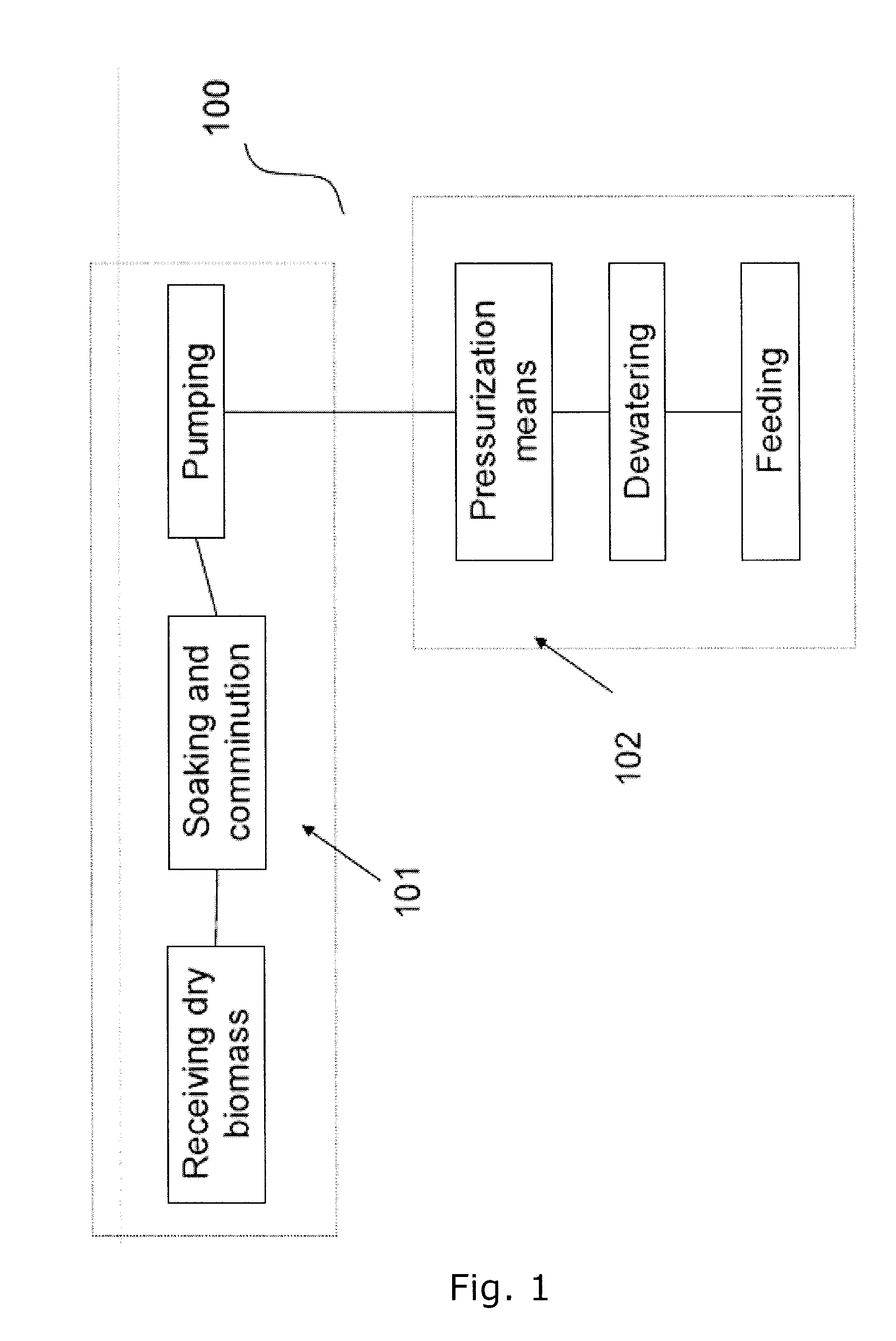
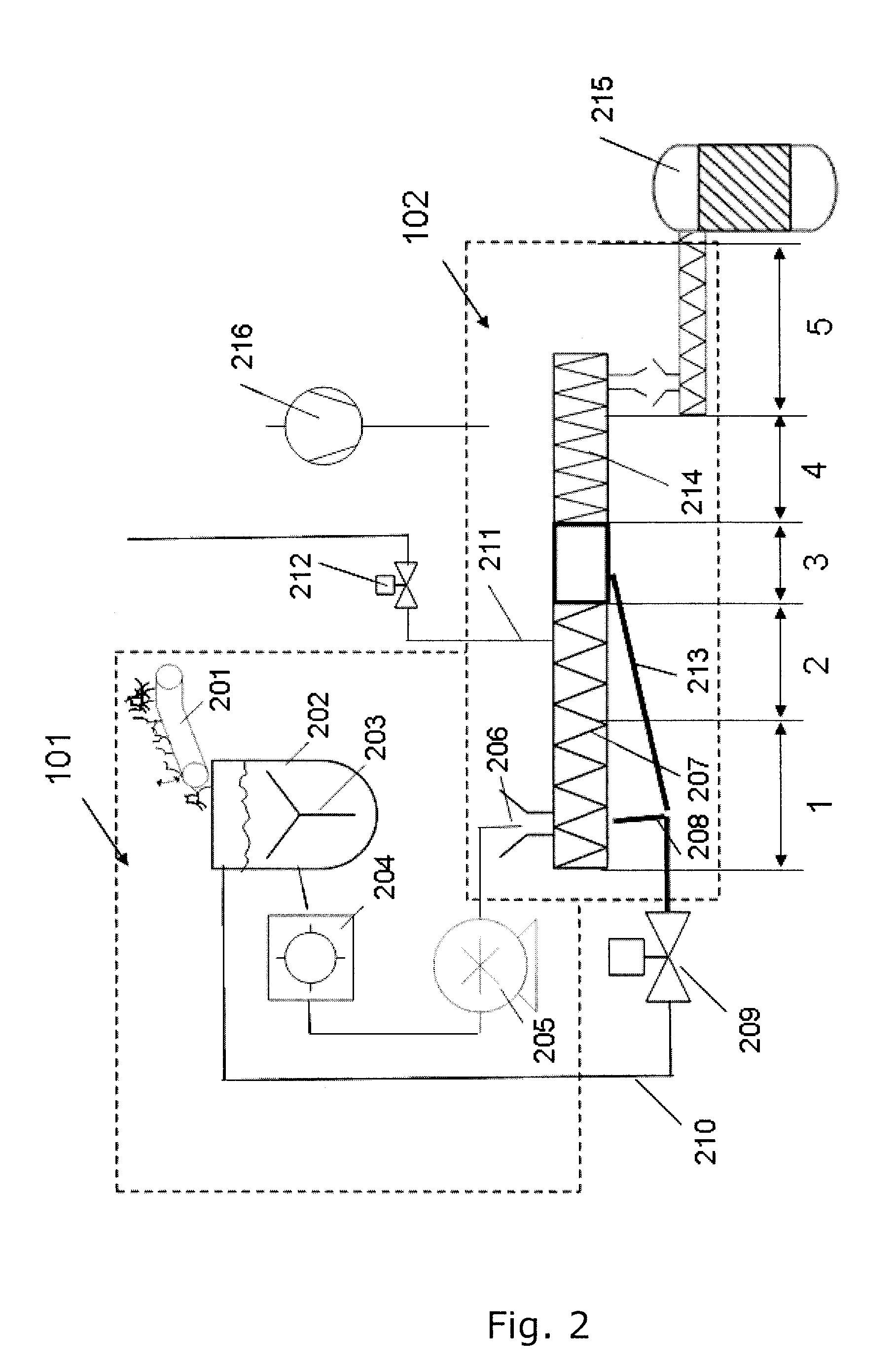
[0086]FIG. 1 shows a block diagram of a biomass pre-treatment system 100 having two major subsystems, namely a pre-processing 101 and an in-feeding 102 to a process reactor. The pre-processing 101 includes means for receiving a dry biomass, soaking and comminuting means of said biomass, i. e. producing a pulp and pumping means for delivering said pulp. The in-feed apparatus 102 according to the invention includes pressurization means for maintaining a pressure higher than the atmospheric pressure, de-watering means for reducing the water content of said pulp and transportation means to feed said pulp into a process reactor.

[0087]In FIG. 2 a schematic representation of biomass pre-treatment system including an apparatus for in-feeding matter to a process reactor according to the present invention is disclosed in further details with respect to the various elements. In the pre-processing subsystem 101 the biomass is collected and transported, e. g. through a convey 201, and introduced...


PUM

PropertyMeasurementUnit
Fractionaaaaaaaaaa
Fractionaaaaaaaaaa
Fractionaaaaaaaaaa

Abstract

The present invention relates to an apparatus, which can be part of a pretreatment (101) system in a plant for the production of fuels derived from plant biomass, e.g. first generation crops, such as grain, sugarcane and corn or second generation crops such as lignocellulosic biomass. The apparatus has the function of in-feeding and dewatering biomass so as to control water content in biomass before the dewatered biomass is introduced into a process reactor (215) in a plant for the production of for example, bio-ethanol. The in-feeding and dewatering processes are carried out at a pressure higher than or equal to the pressure inside the process reactor (215) providing the advantage of a fluid tight sealing of the process reactor and facilitating its continuous feeding.

Description

FIELD OF THE INVENTION[0001]The present invention relates inter alia to a process and apparatus for in-feeding and dewatering biomass so as to control water content in biomass before the dewatered biomass is introduced into a process reactor in order to be heat treated and subsequently fermented. Although the description of the present invention focus on biomass, it is envisaged that the invention is generally applicable to control the water content by applying a in-feed and dewatering process to a material in the form of slurry or pulp comprising mixture of a liquid and a solid matter, said material being typically in suspension in the liquid and has soaked liquid.BACKGROUND OF THE INVENTION[0002]Among fuels derived from plant biomass, ethanol has received particular attention as a potential replacement for or supplement to oil-derived products. Production of ethanol from biomass is normally obtained through the fermentation process of raw biological material rich in sugar or starc...

Claims


Application Information

Patent Timeline
IPC IPC(8): C07C31/08B01J19/00
CPCC08H8/00D21B1/12D21B1/342Y02E50/17D21C7/06D21C11/0007D21C5/00Y02E50/10
Inventor BELDRING, FINNLUKIC, DRAGANHILSTROM, TROELS
Owner BIO GASOL IPR APS
Learn More