Control method for soft switch circuit in switch power source

a control method and power supply technology, applied in the field of switch power supply, can solve the problems of inability to meet the output voltage, device inoperative or damaged, index, etc., and achieve the effect of reducing the overall volume of the circuit, improving the efficiency of the circuit, and simplifying the circui

Inactive Publication Date: 2011-11-17
VERTIV CORP
View PDF6 Cites 15 Cited by
  • Summary
  • Abstract
  • Description
  • Claims
  • Application Information

AI Technical Summary

Benefits of technology

[0020]Advantageous effects of the invention over the prior art are as the following:
[0021]The invention can remedy the drawback inherent in the ARCP soft switch circuit without any additional external circuit and can both offer the original function for implementing a soft switch and overcome the imbalance problem of output power of the positive and negative direct current input voltage sources to thereby avoid a series of problems due to imbalance of the positive and negative direct current input voltages. Moreover, no additional balance circuit will be required to thereby greatly simplify the circuit, reduce the overall volume thereof, improve the efficiency thereof and hence achieve a significant technical effect.

Problems solved by technology

Since semiconductor devices in traditional switch power sources function as hard switches, the sources suffer from a great loss, fail to improve their own efficiencies and thus become less and less competitive for the market due to their bulkiness.
Although the ARCP soft switch circuit is rather satisfactory in terms of the reduced loss of the switching devices and the improved efficiency, this circuit suffers from a significant drawback, i.e., imbalance of power output from the positive and negative direct current input voltage sources and consequent imbalance of positive and negative direct current input voltages, which may result in a series of problems, for example:1) An excessive voltage may cause a device to be inoperative or damaged;2) An output voltage may be asymmetry in positive and negative halves of a cycle, so indexes, e.g., precision, distortion, etc., of the output voltage will not be satisfactory.3) A load fails to function normally.
In summary, a resonant current introduced in the ARCP soft switch circuit between the midpoint N of the positive and negative direct current input voltage sources±½Ud and the output point B of the half bridge circuit may cause inconsistency of output power of the positive and negative direct current input voltage sources±½Ud to thereby result in an offset of their voltages and further a series of problems.
This may be an inevitable and fatal drawback of the ARCP soft switch circuit topology and consequently limit the application scope and reliability thereof.
Although the foregoing method in which an external balance circuit is added can address the imbalance problem of the positive and negative direct current input voltages, it can be apparent that the entire circuit may be complicated and suffer from a raised cost, an increased volume, a lowered efficiency and greatly lowered reliability due to the additional balance circuit.
If output power of the primary power circuit is tens to hundreds of kilowatts, the disadvantages of the additional balance circuit, such as volume, cost, efficiency, reliability, etc. will become more prominent and may even cancel off the benefit from the use of the ARCP soft switch circuit.

Method used


Image

  • Control method for soft switch circuit in switch power source
  • Control method for soft switch circuit in switch power source
  • Control method for soft switch circuit in switch power source

Examples


first embodiment

The First Embodiment

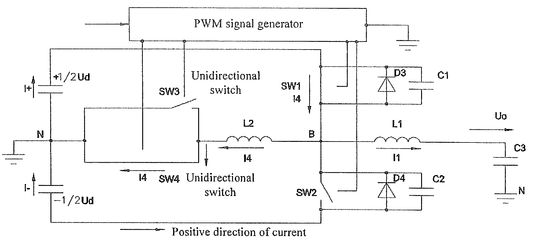
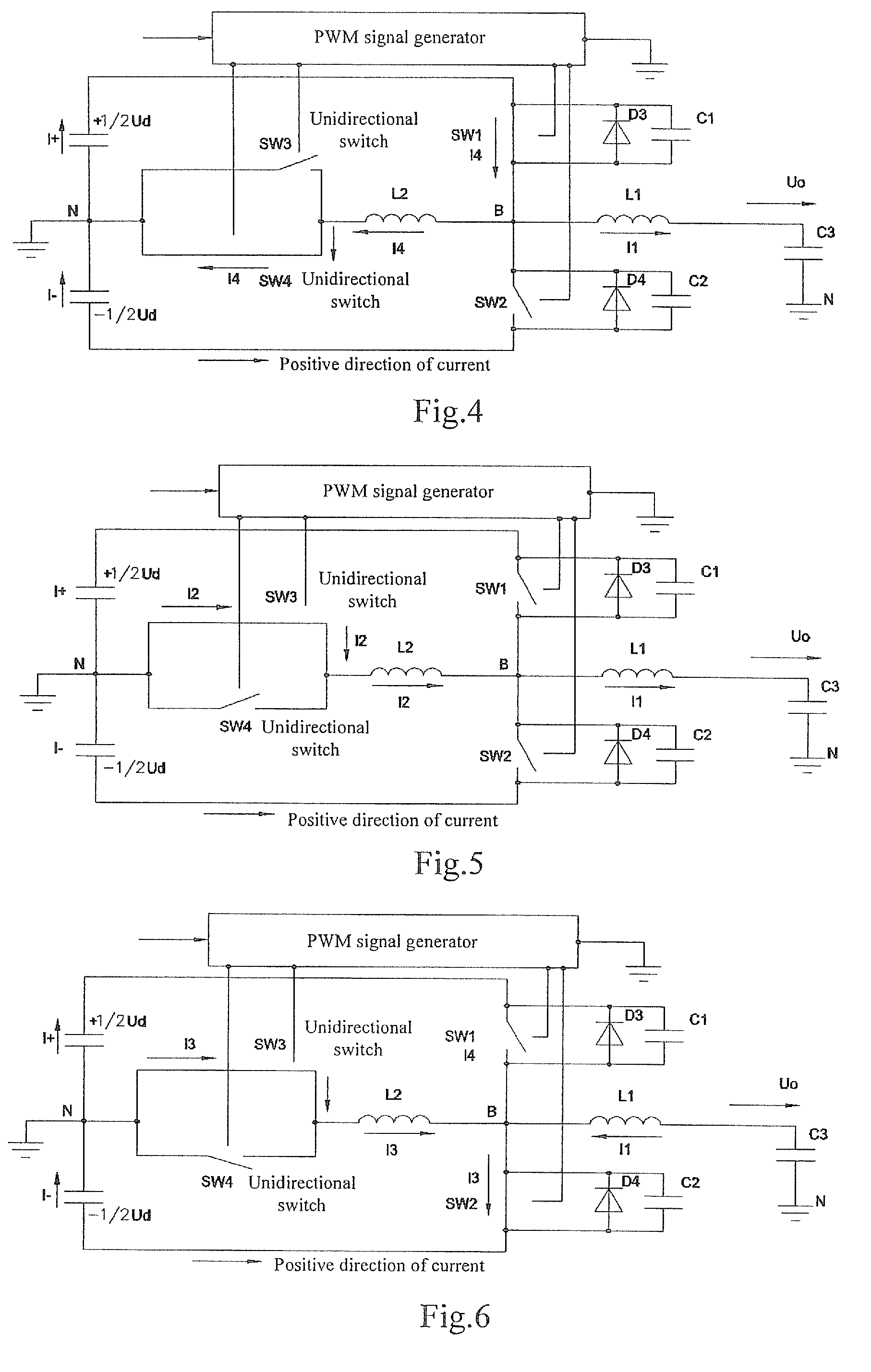
[0036]FIG. 4 illustrates a schematic diagram of a circuit operation status corresponding to a moment when the forward auxiliary switching device SW4 is closed in the positive half of a cycle of a soft switch circuit according to the embodiment of the invention, FIG. 5 illustrates a schematic diagram of a circuit operation status corresponding to a moment when the backward auxiliary switching device SW3 is closed in the positive half of a cycle of the soft switch circuit according to the embodiment of the invention, FIG. 6 illustrates a schematic diagram of a circuit operation status corresponding to a moment the backward auxiliary switching device SW3 is closed in the negative half of a cycle of the soft switch circuit according to the embodiment of the invention, and FIG. 7 illustrates a schematic diagram of a circuit operation status corresponding to a moment the forward auxiliary switching device SW4 is closed in the negative half of a cycle of the soft switch...

second embodiment

The Second Embodiment

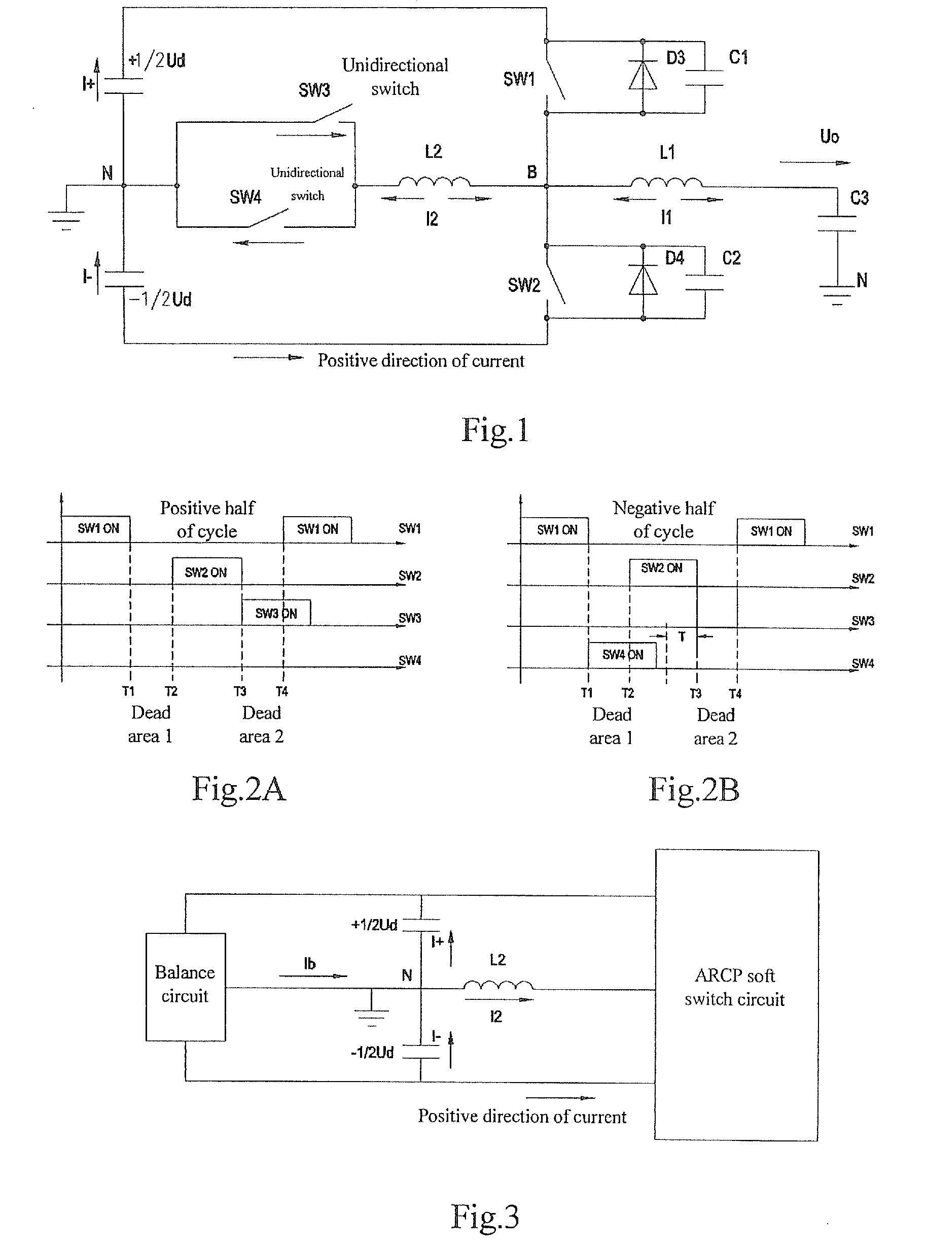
[0041]A timing control for the switching devices is performed as in the schematic diagrams of switch logics illustrated in FIG. 9A and FIG. 9B. That is, under the control logic of the ARCP soft switch circuit, SW4 is closed after SW1 is closed, and opened during a period of first dead area [T1˜T2] in the positive half of a cycle to thereby generate the balance current I4 with the same magnitude as and in the opposite direction to the subsequently generated resonant current I2; and SW3 is closed after SW2 is closed, and opened during a period of second dead area [T3˜T4] in the negative half of a cycle to thereby generate the balance current I3 with the same magnitude as and in the opposite direction to the subsequently generated resonant current I2.

third embodiment

The Third Embodiment

[0042]A timing control for the switching devices is performed as in the schematic diagrams of switching logics illustrated in FIG. 10A and FIG. 10B. That is, under the control logic of the ARCD soft switch circuit, SW4 is closed after SW1 is closed, and opened prior to the moment T1 when SW1 is opened in the positive half of a cycle to thereby generate the balance current I4 with the same magnitude as and in the opposite direction to the subsequently generated resonant current I2; and SW3 is closed after SW2 is closed, and opened prior to the moment T3 when SW2 is opened in the negative half of a cycle to thereby generate the balance current I3 with the same magnitude as and in the opposite direction to the subsequently generated resonant current I2.

[0043]In the context of the invention, the two unidirectional auxiliary switching devices are defined as forward and backward auxiliary switching devices respectively to distinguish between their uni-directivity of co...


PUM


Abstract

The present invention discloses a control method for a soft switch circuit in a switch power source, which generates an alternating primary power filter current by controlling first and second primary power switching devices to be closed and opened, and generates an intermittent alternating resonant current in the same direction as the primary power filter current in a resonant branch by controlling forward and backward auxiliary switching devices to be closed and opened to thereby achieve closing of the first and second primary power switching devices at a zero voltage, and which generates a balance current with the same magnitude as and in the opposite direction to the resonant current in the resonant branch in at least a period of time during the resting of the resonant current by further controlling the forward and backward auxiliary switching devices to be closed and opened to thereby achieve an average current of zero across the resonant branch in a switching cycle. Without any additional balance circuit, this control method can address the imbalance problem of output power of the positive and negative direct current input voltage sources in a soft switch circuit of an existing switch power source.

Description

FIELD OF THE INVENTION[0001]The present invention relates to a switch power source, and in particular to a control method for a soft switch circuit in a switch power source.BACKGROUND OF THE INVENTION[0002]Switch power sources are currently in the trend of evolving towards miniaturization at a high frequency, a high power density, a high efficiency and a low cost. Since semiconductor devices in traditional switch power sources function as hard switches, the sources suffer from a great loss, fail to improve their own efficiencies and thus become less and less competitive for the market due to their bulkiness. In view of limitations by the development in the industry of semiconductor devices, the cost, etc., a soft switch circuit topology has been an option for the majority of switch power source manufacturers to improve product competitiveness. There are numerous researches and patents on soft switch circuits, and one of them is a Auxiliary Resonant Commutated Pole (ARCP) soft switch...

Claims


Application Information

Patent Timeline
Patent Type & Authority Applications(United States)
IPC IPC(8): H01H33/59
CPCH02M7/538Y02B70/1441H02M2007/4811Y02B70/10H02M7/4811
Inventor ZHANG, CHUNTAOZHANG, XIAOFEIXIAO, XUELI
Owner VERTIV CORP
Why Eureka
Try Eureka