Multimodal depth-resolving endoscope

a multi-modal, endoscope technology, applied in the field of endoscopy, can solve the problems of multiple chromogens, difficult to separate and quantitate, and affecting the quality of images

Inactive Publication Date: 2011-11-17
AXELROD NOEL +2
View PDF6 Cites 59 Cited by
  • Summary
  • Abstract
  • Description
  • Claims
  • Application Information

AI Technical Summary

Benefits of technology

[0042]The imaging system enables in-depth resolving capabilities for the detection of undersurface pathologies and structures such as blood vessels, urine vessels etc that lie under the tissue surface, during minimal invasive surgery procedures thus providing a safety margin for the surgeon....

Problems solved by technology

This gives adequate diagnostic information, although the image quality may be compromised by both the number of (intact) elements within the fiber bundle and the light losses, which become significant when the indivi...

Method used


Image

  • Multimodal depth-resolving endoscope
  • Multimodal depth-resolving endoscope
  • Multimodal depth-resolving endoscope

Examples


Embodiment Construction

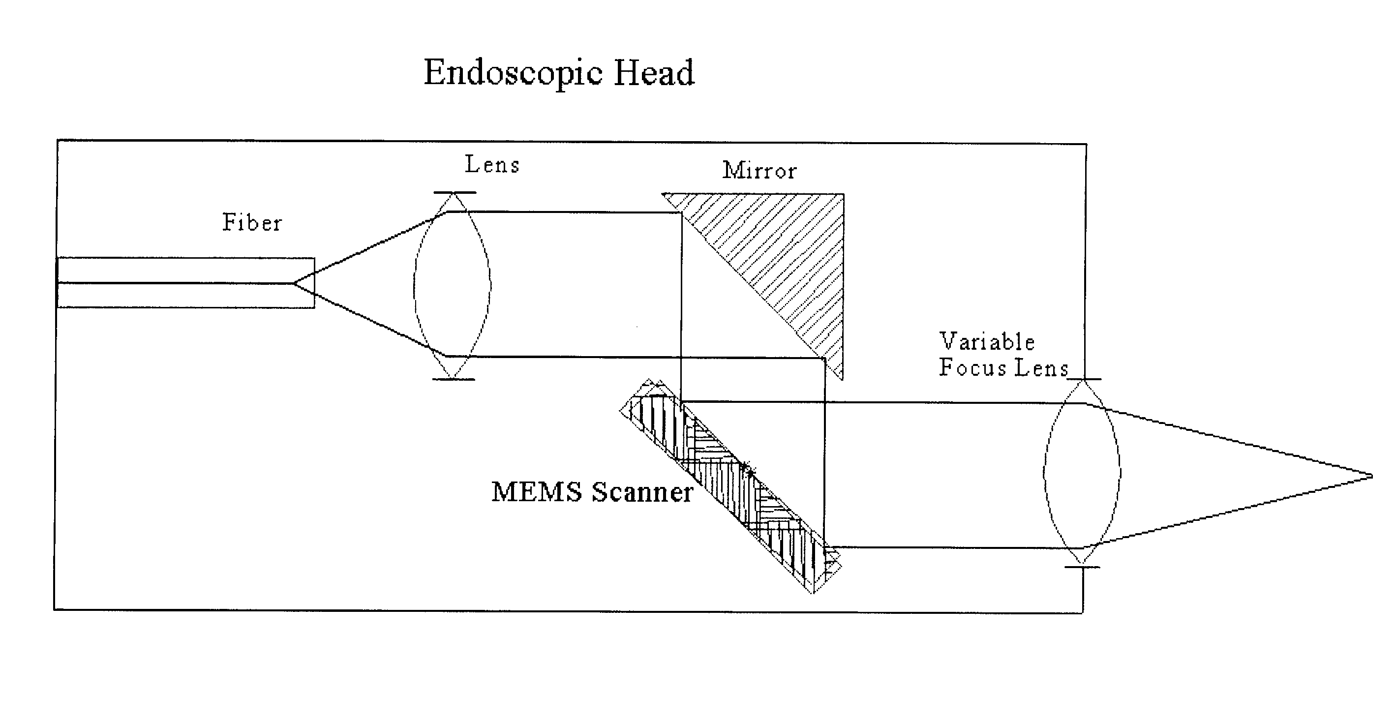
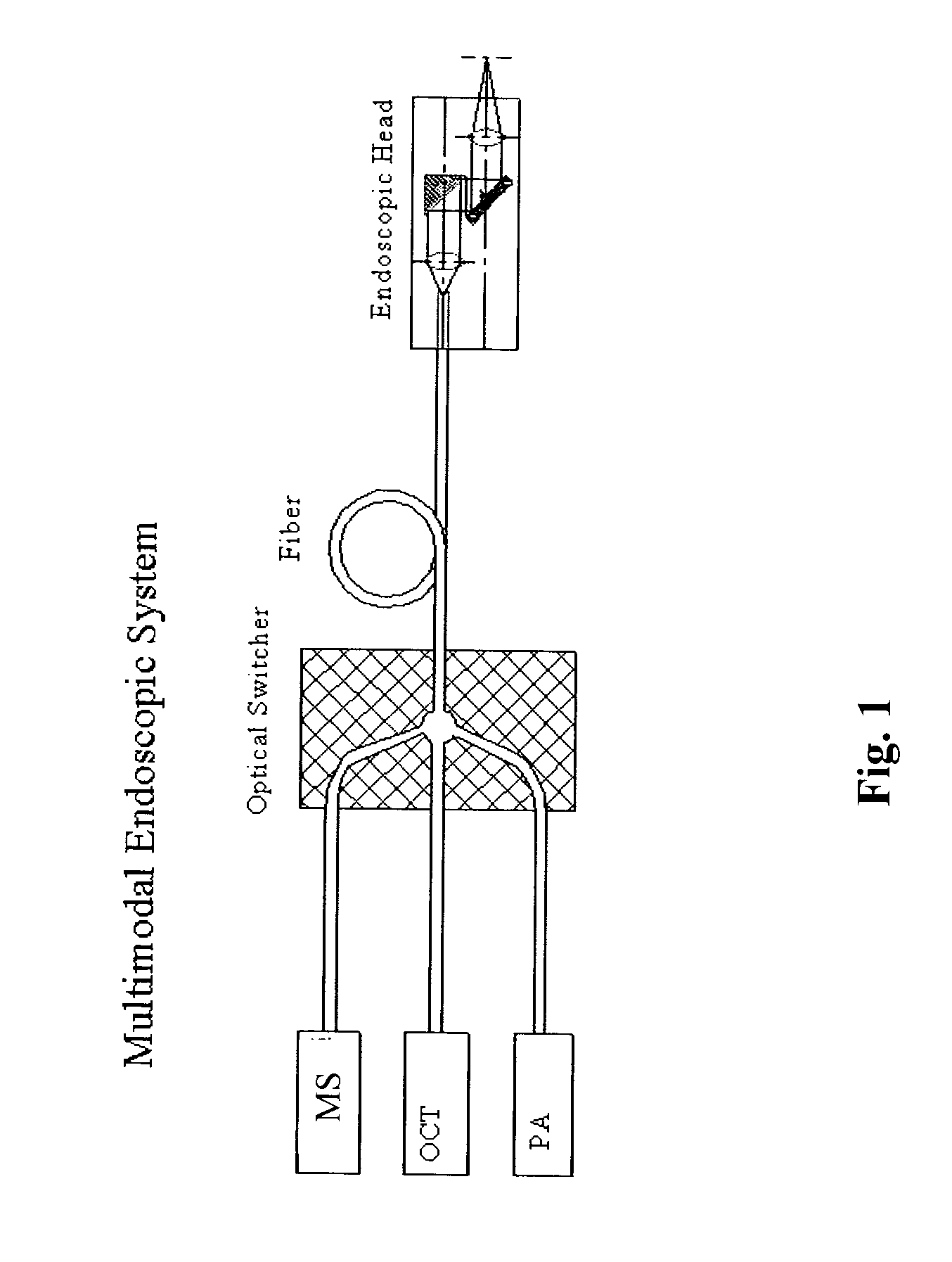
1 shows a schematic illustration of a multimodal endoscoping system according to one embodiment of the invention, combining Photoacoustic (PA), Optical Coherence Tomography (OCT) and Multi-Spectral (MS) imaging modalities, wherein all modalities are connected to an endoscopic head via fiber optics and an optical switcher.

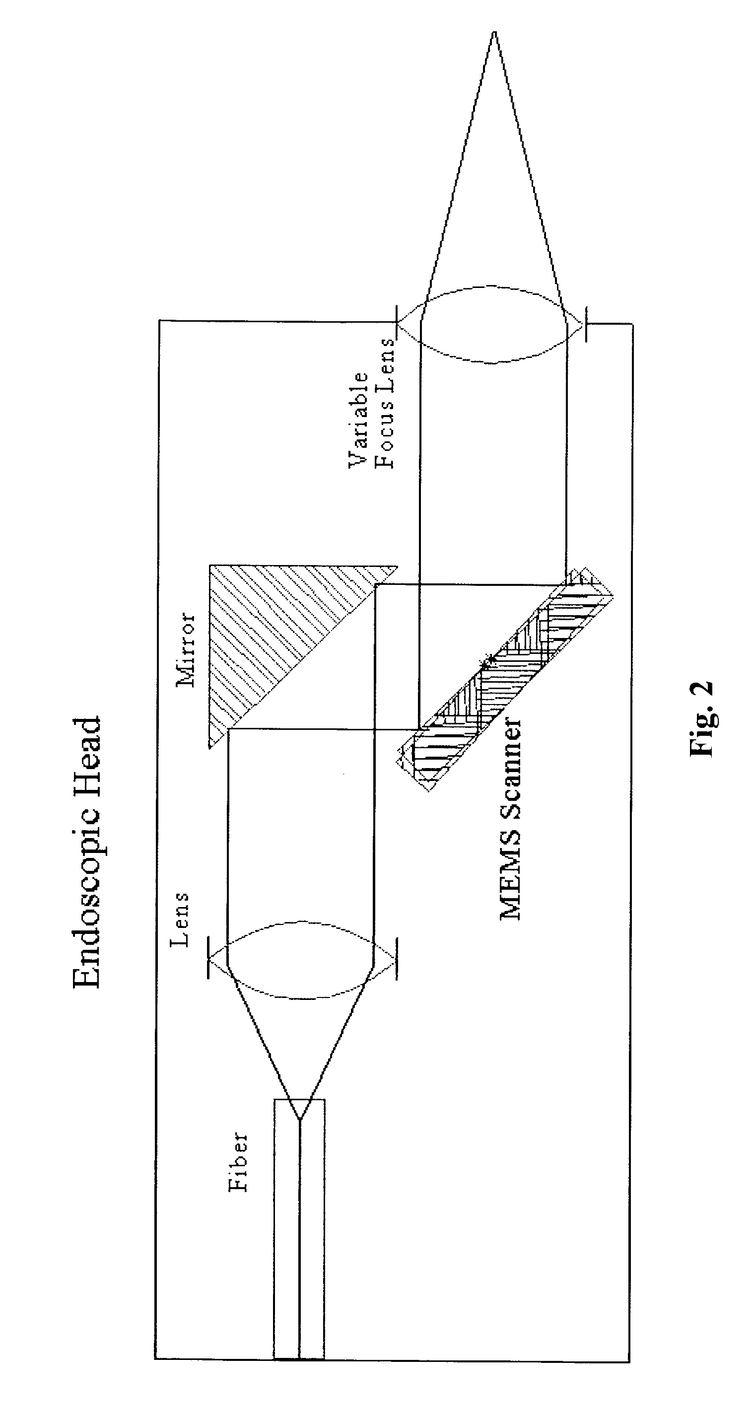
[0065]FIG. 2 depicts a scheme of the Microelectromechanical Systems (MEMS) based multimodal endoscope head comprising a MEMS scanner shown in FIG. 1.

[0066]FIG. 3 is a schematic illustration of a forward-looking endoscopic Micro-Opto-Electro-Mechanical Systems (MOEMS) head module equipped with a MEMS scanner. All parts are designed to be aligned by location in tight tolerance polyimide tubing.

[0067]FIG. 4 shows a block diagram of the architecture of the Multimodal Endoscopic System of the invention comprising a MOEMS scanning module equipped with a MEMS scanner unit with control electronics (ASIC) that is responsible for synchronization of lasers and MEMS scanner. Th...


PUM


Abstract

A fiber-optic multimodal multi-spectral (MS), Optical Coherence Tomography (OCT), photoacoustic (PA) endoscope with beam scanning by a two-dimensional Microelectromechanical systems (MEMS) scanner present in the endoscopic head, combined in a synergetic way in a single endoscopic system. The PA, OCT and MS light sources are coupled to the endoscopic head through an optical switcher. Using a single optical endoscopic head and an electro-optical switch the endoscope of the invention is capable of sequential or parallel MS, OCT and PA imaging. The endoscope provides real-time imaging with a rate of 5 to 60 frames per second for each of the three imaging modalities.

Description

TECHNICAL FIELD[0001]The present invention relates to endoscopy in general and to depth-resolving, multimodal endoscopy in particular.BACKGROUND ART[0002]Endoscopy and Depth Resolved Endoscopy:[0003]Endoscopy is a vital, yet minimally invasive, operative procedure, increasingly employed for both diagnosis and management of many medical and surgical conditions. There are broadly two classes of purely optical endoscope. The first endoscope developed in the 1960s uses a long flexible fiber-optic coupling between the remote lesion site and the user. This gives adequate diagnostic information, although the image quality may be compromised by both the number of (intact) elements within the fiber bundle and the light losses, which become significant when the individual fibers of a bundle decrease below 6-8 μm diameter.[0004]An alternative class of endoscope uses a thin rigid tube enclosing a distributed lens system. These instruments are optically superior to their fiber bundle counterpart...

Claims


Application Information

Patent Timeline
IPC IPC(8): A61B6/00
CPCA61B1/00096A61B1/00172A61B5/0066A61B5/6852A61B5/0086A61B5/0095A61B5/0075A61B5/0035A61B2018/20359A61B2018/207A61B2018/2211
Inventor AXELROD, NOELLICHTENSTEIN, AMIRSARUSI, GABBY
Owner AXELROD NOEL
Why Eureka
Try Eureka