
Wet Granulation System Comprising at Least One Ultrasonic Nozzle

a technology of ultrasonic nozzle and wet granulation system, which is applied in the direction of vibration, colloidal chemistry, transportation and packaging, etc., can solve the problems of superior growth, over-sized granule production, and poor initial liquid binder distribution, so as to improve the flow rate and the distribution of small particles is small and the effect of good flow ability

Inactive Publication Date: 2011-11-24
ASTRAZENECA AB
View PDF1 Cites 2 Cited by
  • Summary
  • Abstract
  • Description
  • Claims
  • Application Information

AI Technical Summary

Benefits of technology

[0017]The object mentioned above is achieved by providing a system for uniform distribution of a liquid binder onto the surface of finely particulate solids of at least one pharmaceutical product. In preferred embodiments, finely particulate refers to a material having a mean particle, preferably measured by sieve analysis, of less than 250 μm, preferably less than 100 μm. The system comprises a substantially circular mixer, provided with rotating means in the lower part, arranged to enable the said solids to rotate along the periphery of the mixer in a first rotational movement, and at least one ultrasonic nozzle connected to a feeding device providing the liquid binder, and arranged to distribute the said liquid binder in the form of droplets onto the surface of the said solids during their rotational movement. By using an ultrasonic nozzle for distribution of the liquid binder in a very accurate way in the form of droplets not being under pressure, production of granules with good flow ability, small size distribution, porous structure and good compressibility are enabled. Since the thus produced granules are small and in a unitary size, there is no need for a chopper chopping the granules to smaller size, for producing small granules.
[0018]Ultrasonic atomization involves the formation of fine droplets by the vibration of a thin liquid binder film on a vibrating surface. The thus formed droplets are then ejected from the vibrating surface into the surrounding as a dense fog, falling down by gravity avoiding dens impact. If the pharmaceutical solids flow is sufficient high and a proper liquid binder flow is used, a short wetting time is obtained leading to improved control of the growth of the granules. Since the surface of the nozzle is vibrating no pharmaceutical solids is stuck to the nozzle and disturbing the spray pattern. Further, production of granules that preferably comprise gelling polymers with good flow ability, small size distribution, porous structure and good compressibility are enabled. Further, the use of ultrasonic nozzles in granulation processes also have an advantage regarding the size of the droplets, since the droplets are more even in size, and the size are controlled in a very accurate way by changing the amplitude—input energy, and the liquid binder flow.
[0020]By bringing the solids into a rotational movement, with rotational movements in several directions, the area of the solids are exposed to the liquid binder in an efficient way, resulting in even distribution of the liquid binder on the whole surface of each solid.

Problems solved by technology

If the liquid binder droplet size is much larger than the size of the primary particles, this results in growth by the immersion mechanisms instead of the distribution mechanism that results in production of over sized granules.
Liquid binder distribution by the pour-on method is solely dependent on mechanical mixing which is why this method causes a very poor initial liquid binder distribution.
This uneven liquid binder distribution causes local areas of high moisture content and superior growth while other areas remain ungranulated.
Although the pour-on method possesses some advantages including the ease of processing and the short process time, as a consequence of the above mentioned disadvantage with is uneven distribution of the liquid binder, this method is not applicable where accurate and even distribution of the liquid binder is critical to the quality of the thus produced granules.
Although the spray-on method has advantages compared to the pour-on method, it is possessed with limitations.
The pressure cannot be too low, since it results in clogging of the nozzle and in the granulation time being too long.
Another disadvantage with the spray-on method is that the droplets show a wide size distribution, causing a wide granule size distribution.
Further, the need of the liquid binder to be added under pressure results in loss of pharmaceutical solids in filters and on the walls of the equipment.
As a result of the facts described above, it is difficult to control the droplets size.
Increasing the pressure leads to smaller droplet size and higher flow rate but more over wetting due to dens impact of droplets.
Decreasing the nozzle orifice decreases the liquid binder flow and increases the risk for clogging of the nozzle.
Further, a substantial pressure added to the liquid binder thus dispersing the pharmaceutical solids, results in the bottom and the wall of the container becoming wet.
As a result, it is difficult to achieve uniform granules with narrow particle size distribution.
If the pressure is reduced, the liquid binder droplets become larger with the drawback that humidification becomes uneven.
Another problem is that the dispersed pharmaceutical solids stuck to the nozzle disturbing the spray pattern with uneven humidification as a is result.
Further, the over pressure also create a dim of pharmaceutical solids clogging any filter unit connected to the granulation mixer, and it also decreases the yield for the granulation.
Yet another problem arises with some formulations, i.e. formulations containing different gelling polymers.
Formulations comprising gelling polymers can be very sensitive to over wetting since the pharmaceutical solids swells during granulation and create lumps in different sizes which can be difficult to mill after drying, resulting in lower yield.
Long time generates larger lumps that can be difficult to dry and mill.
These lumps tend to be very hard after the drying process, resulting in granules with low compressibility not being suitable for use in for example a tablet pressing process.

Method used


Image

  • Wet Granulation System Comprising at Least One Ultrasonic Nozzle
  • Wet Granulation System Comprising at Least One Ultrasonic Nozzle
  • Wet Granulation System Comprising at Least One Ultrasonic Nozzle

Examples


Embodiment Construction

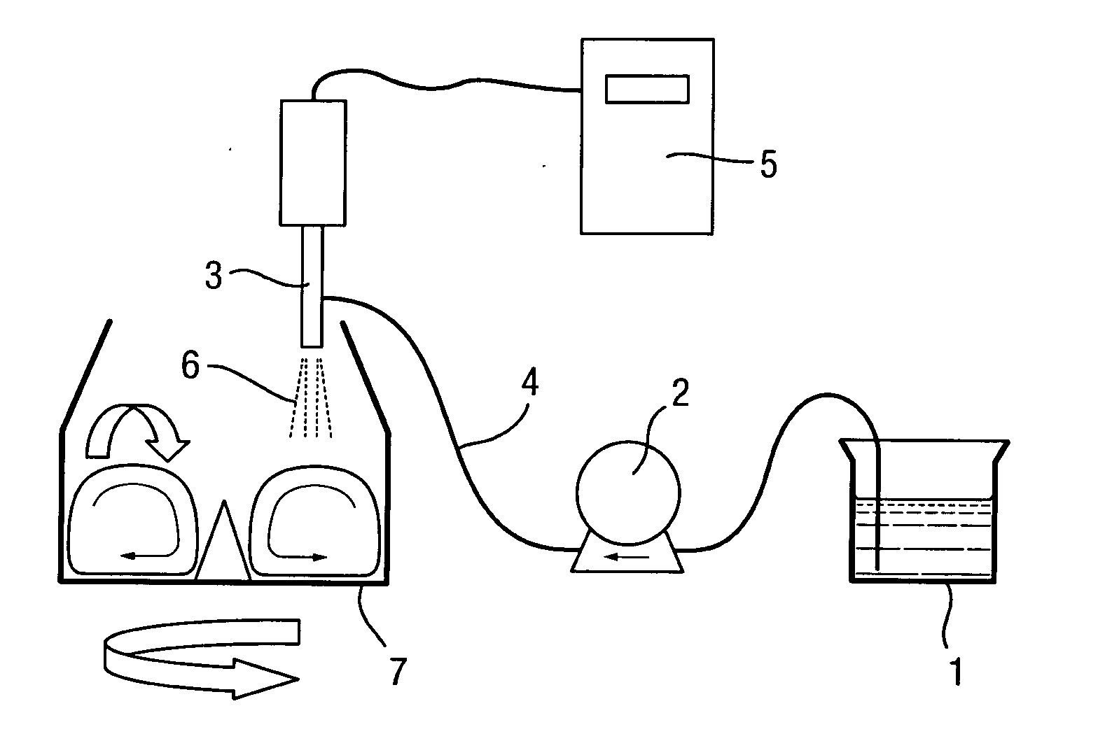
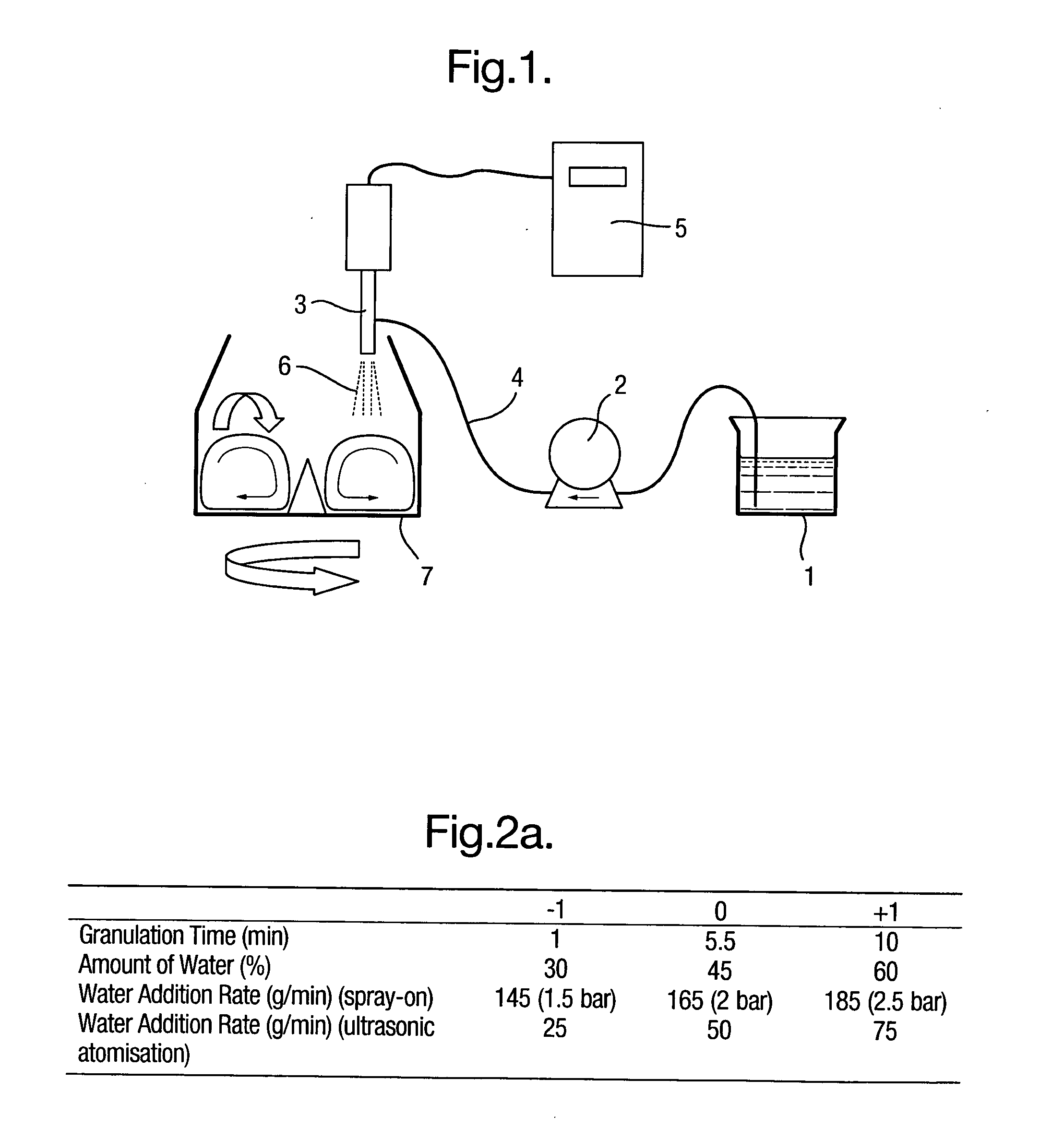
[0037]FIG. 1 shows an embodiment of the present invention. An ultrasonic atomizer nozzle 3 is used in a mixer 7 with rotating means, i.e. a bottom drive impeller. Fine particulate solids of at least one pharmaceutical product, i.e. in the form of pharmaceutical solids material, are added in a mixer 7, and an appropriate amount of liquid binder 1, i.e. an aqueous or an organic solution, is applied from above by an ultrasonic atomizer equipped with an atomizer nozzle 3.

[0038]During operation, the system works as follows. A fixed amount of granulation liquid binder 1 is supplied by means of a metering pump 2 (for example a gear pump) to a nozzle 3 via a tube 4. Appropriate ultrasonic vibrations are imparted to the nozzle 3 by a control unit 5 to discharge droplets 6 into a mixer 7. By using a gear pump together with an ultrasonic-unit, the flow of liquid binder 1 is controlled very accurately and thus, as a consequence, indirectly controlling the granule growth.

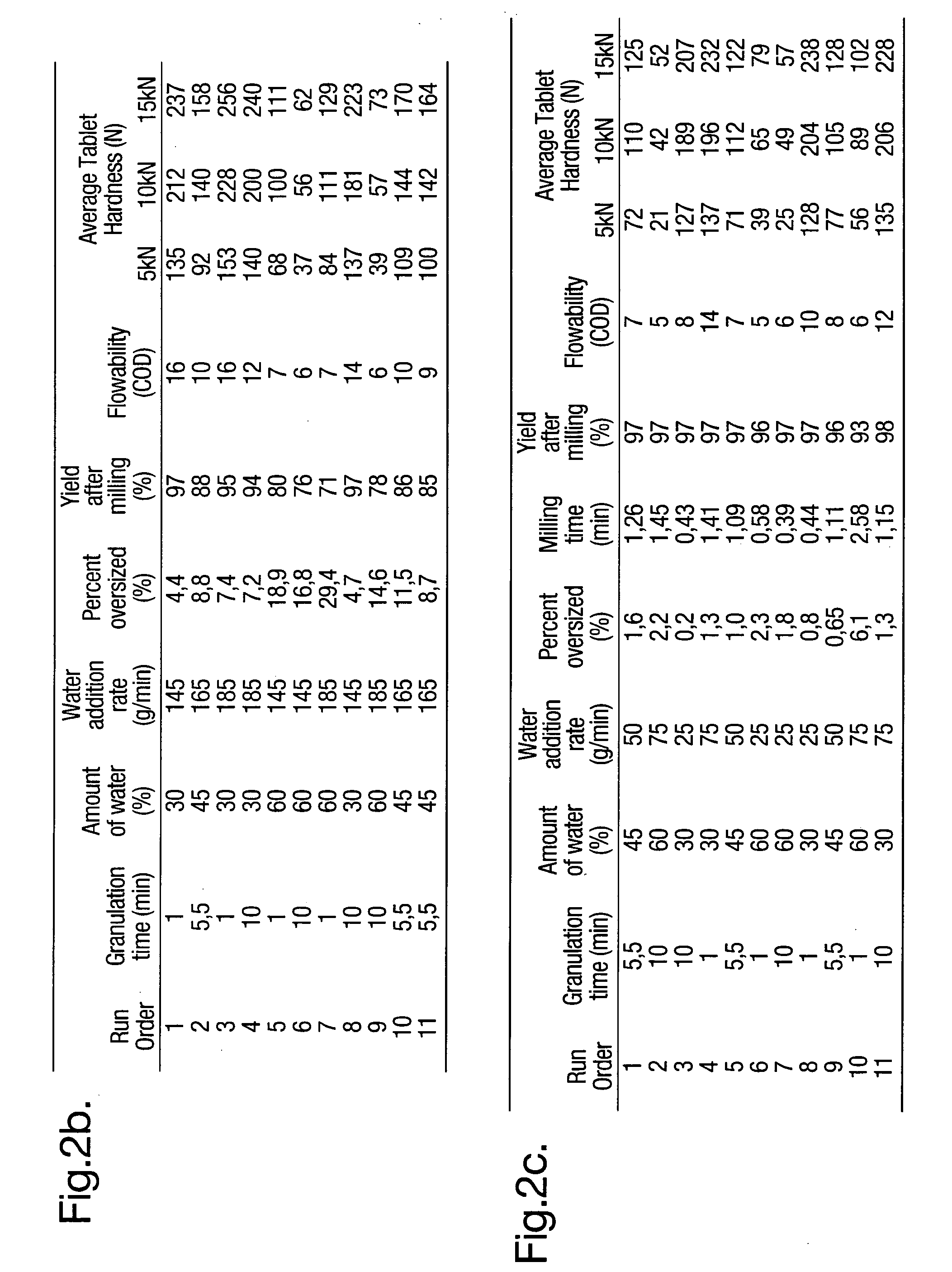
[0039]In FIGS. 2, 3 and ...


PUM

PropertyMeasurementUnit
diameteraaaaaaaaaa
diameteraaaaaaaaaa
temperatureaaaaaaaaaa

Abstract

The present disclosure relates to a system for uniform distribution of a liquid binder onto a surface of particulate solids of at least one pharmaceutical product. The system comprises a substantially circular mixer, provided with rotating means in a lower part, configured to rotate the solids along a periphery of the mixer in a first rotational movement, and at least one ultrasonic nozzle connected to a feeding device providing the said liquid binder, and configured to distribute the liquid binder as droplets onto the surface of the solids during their rotational movement.

Description

TECHNICAL FIELD[0001]The present invention relates to a system for uniform distribution of a liquid binder onto the surface of finely particulate solids of at least one pharmaceutical product.[0002]The invention further relates to use of such a system, and to a method for uniform distribution of a liquid binder onto the surface of finely particulate solids.BACKGROUND OF THE INVENTION[0003]Distribution of a liquid binder onto the surface of a pharmaceutical solids, finely particulate solids of a pharmaceutical product, so called wet granulation, is widely used within the pharmaceutical industry for the formulation of solid dosage forms. Wet granulation is a size enlargement process in which liquid binder is used to agglomerate solid particles. The particles in the pharmaceutical solids are bound together by the liquid is binder through capillary and viscous forces until drying where more permanent bonds are formed.[0004]The granulation process enlarges particles of pharmaceutical sol...

Claims


Application Information

Patent Timeline
Patent Type & Authority Applications(United States)
IPC IPC(8): A61K9/28B05C5/00
CPCA61K9/1694A61K9/2095B01J2/18B01J2/10B01J2/006B01J2/12A61K9/16B01F23/50B01F33/80
Inventor BUZSAKY, FERENC
Owner ASTRAZENECA AB
Learn More