

Electrical conductive member and polymer electrolyte fuel cell using the same
- Summary
- Abstract
- Description
- Claims
- Application Information
AI Technical Summary
Benefits of technology
Problems solved by technology
Method used
Image

Examples
first embodiment
[0079]The following is a description of an electrical conductive member, a method for manufacturing the electrical conductive member, and a polymer electrolyte fuel cell according to the first embodiment of the present invention with reference to the drawings. Note that, the present invention is not limited only to the following embodiment. In the drawings, dimensional ratios are magnified for the convenience of explanation of the present invention, and may be different from the actual ratios.
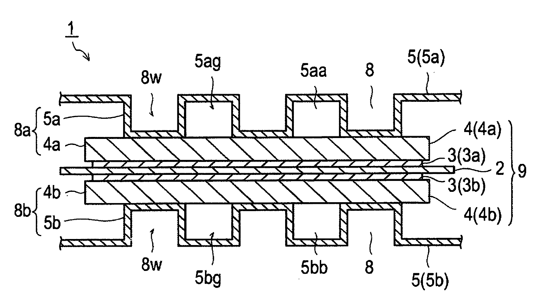
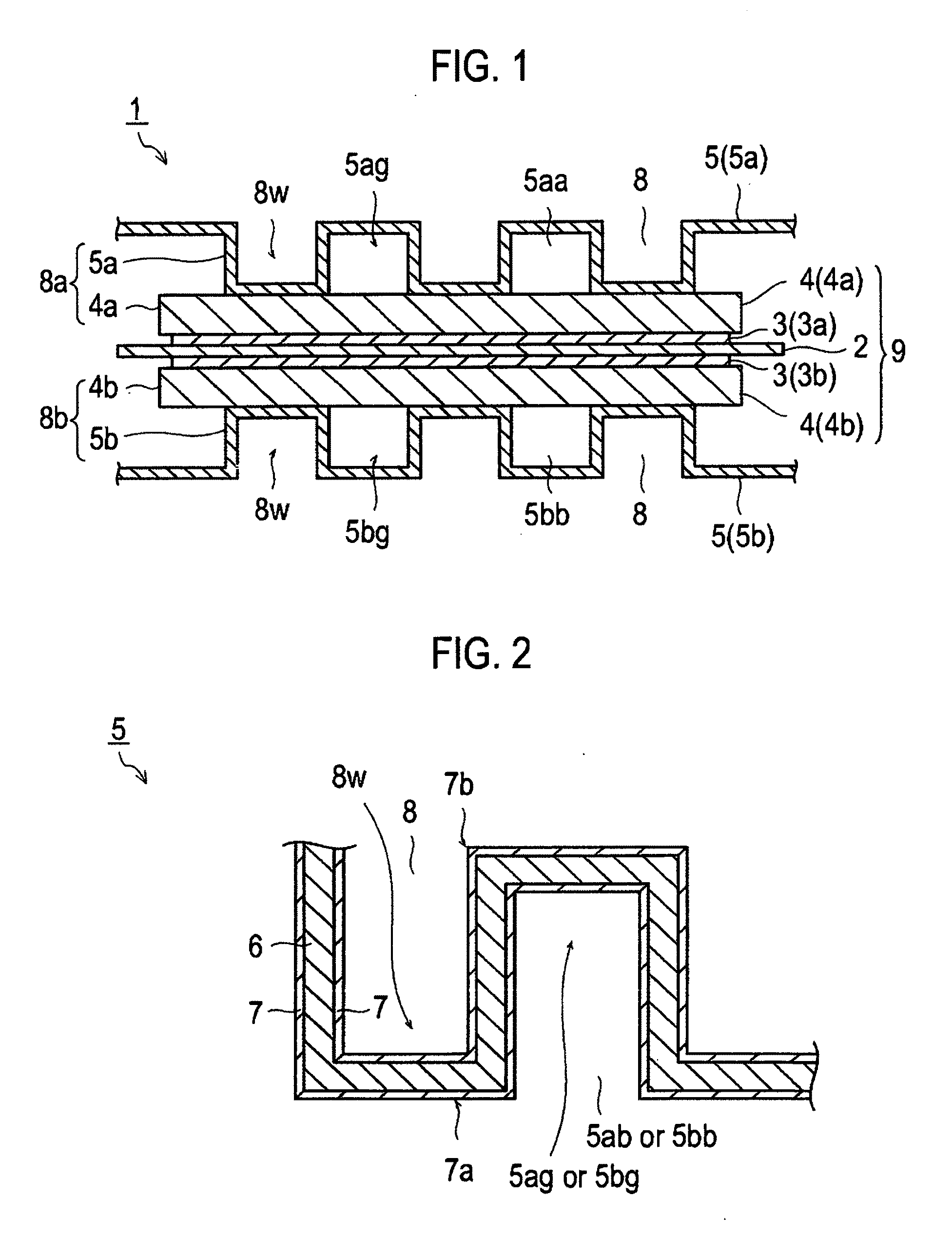
[0080]An electrical conductive member (electrical conductive structure) according to the present embodiment includes a metal substrate, and an electrical conductive carbon layer that contains electrical conductive carbon and is provided on at least one surface of the metal substrate. An intensity ratio R (ID / IG) of a peak intensity (ID) of D-band to a peak intensity (IG) of G-band of the electrical conductive carbon layer, which is measured by a Raman scattering spectroscopic analysis, is 1.3 o...
example i-1
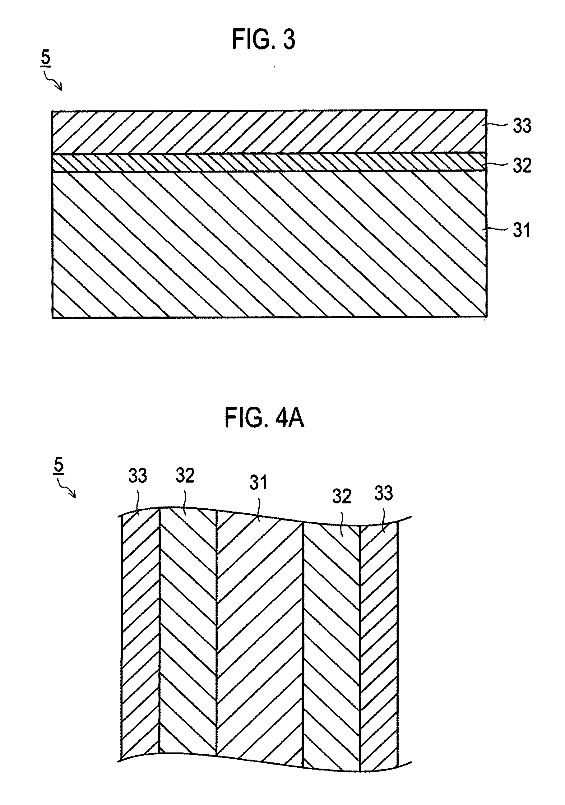
[0225]A stainless steel plate (SUS316L) was prepared as a constitution material of the metal substrate 31 constituting the electrical conductive member. The thickness of the stainless steel plate was 100 μm. The stainless steel plate was washed by ultrasonic waves in an ethanol aqueous solution for three minutes as a pretreatment. Next, the washed stainless steel plate was placed in a vacuum chamber, and subjected to an ion bombard treatment by Ar gas, so as to remove an oxide film on the surface thereof. Note that, both the pretreatment and the ion bombard treatment were performed on both surfaces of the stainless steel plate.
[0226]Then, by use of an unbalanced magnetron sputtering method, the middle layer 32 constituted by Cr with the thickness of 0.2 μm was formed on each surface of the stainless steel plate using Cr as a target, while applying negative bias voltage of 50 V to the stainless steel plate.
[0227]Further, by use of the UBMS method, the electrical conductive carbon lay...
example i-2
[0228]The electrical conductive member in Example I-2 was prepared by similar operations to those in Example I-1 except that the negative bias voltage (absolute value) applied at the time of the formation of the electrical conductive carbon layer 33 was 140 V.
PUM
 Abstract
Description
Claims
Application Information