Light source device, lighting device and image display device using such light device

a light source device and light source technology, applied in the field of blue laser light source devices, can solve the problems of narrow reproduction range, cumbersome maintenance, narrow system, etc., and achieve the effect of superior color rendering properties

Inactive Publication Date: 2011-12-01
PANASONIC INTELLECTUAL PROPERTY MANAGEMENT CO LTD
View PDF9 Cites 84 Cited by
  • Summary
  • Abstract
  • Description
  • Claims
  • Application Information

AI Technical Summary

Benefits of technology

[0029]According to the present invention, by using a solid-state light source which has a long life and does not require mercury, it is possible to realize a light source device that can be used in a lighting dev

Problems solved by technology

However, in a case where lamps are used as a light source, there are problems in that: the life of the light source is short, which results in cumbersome maintenance; the optical system tends to be complicated since white light composed of a continuous spectrum is split into three primary colors of red, green, and blue; and the color reproduction range is narrow.
However, there is a problem in that since the light emission brightness is low per unit area in a light emitting part, it is difficult to obtain a bright lighting device.
Meanwhile, a laser light source has a problem in that speckle noise occurs due to high interference, which results in a deteriorated image quality.
On the other hand, with respect to the green wavelength range, high output semiconductor lasers have not been put to practical use to date.
However, these lasers have a characteristic that when the oscillation wavelength becomes long, the light emission efficiency is reduced, resulting in difficulty in obtaini

Method used


Image

  • Light source device, lighting device and image display device using such light device
  • Light source device, lighting device and image display device using such light device
  • Light source device, lighting device and image display device using such light device

Examples


embodiment 1

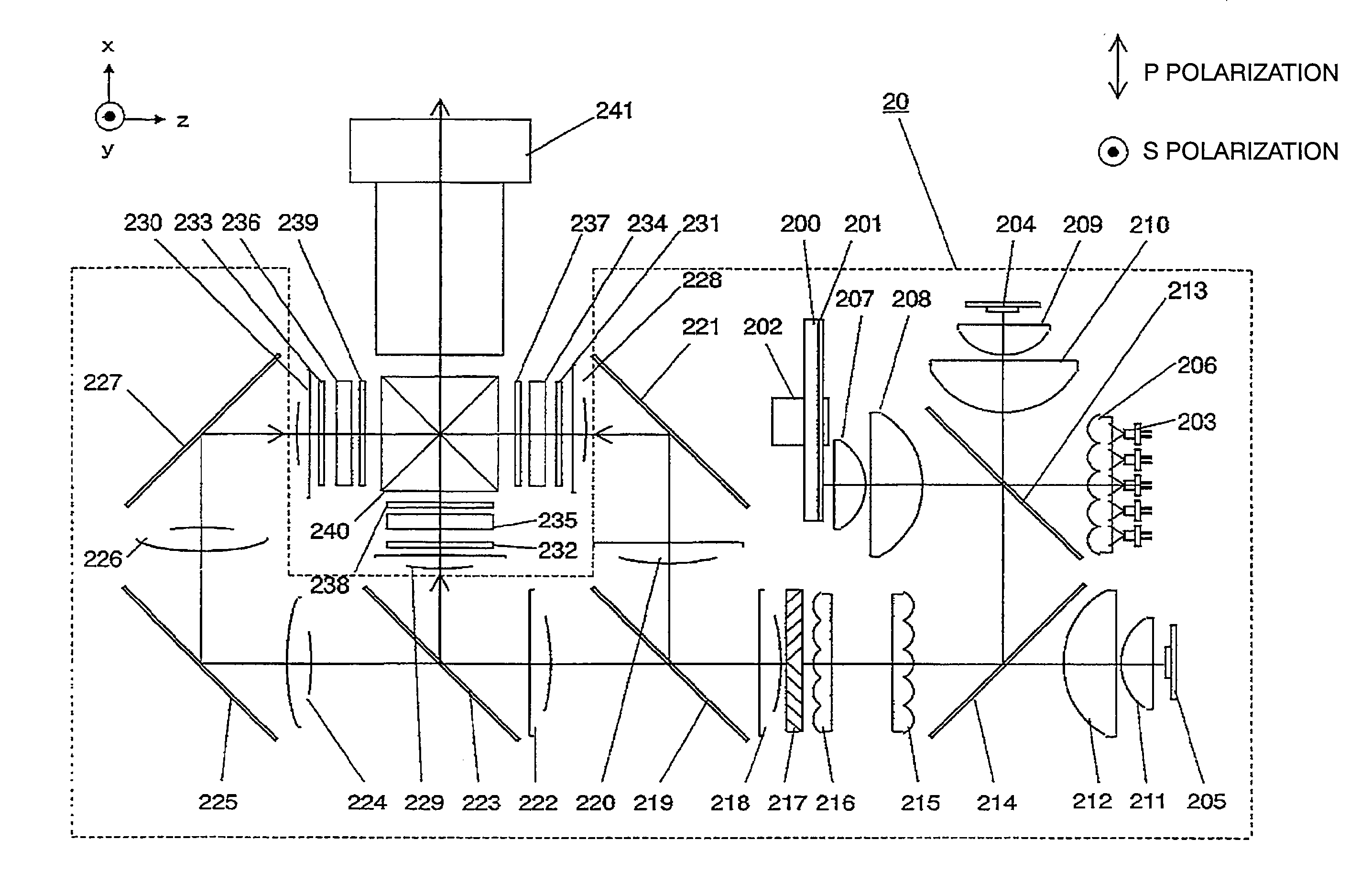
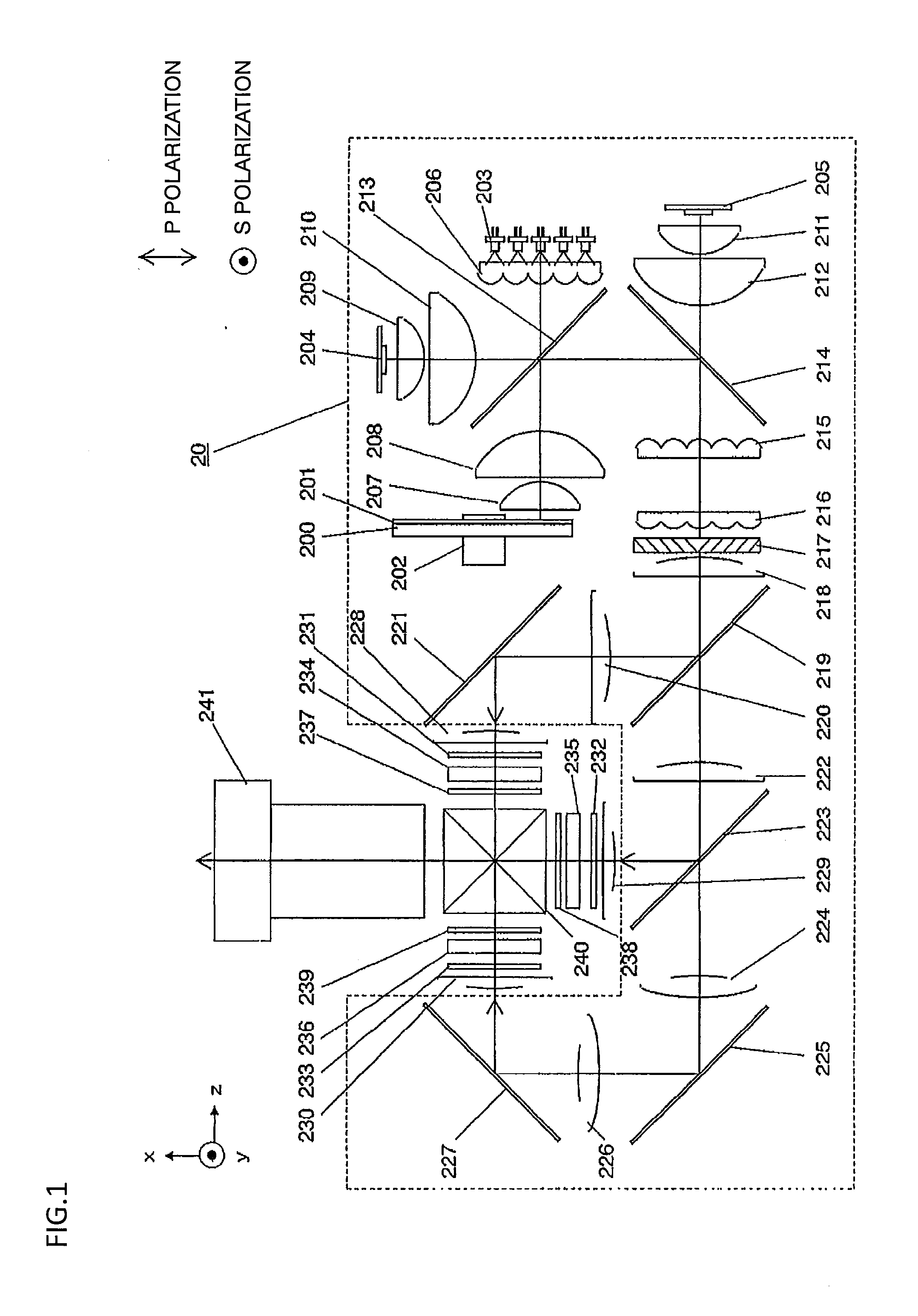
[0043]FIG. 1 shows a configuration of a light source device, and a lighting device and an image display device using the light source device according to a first embodiment. The image display device includes a lighting device 20 and other optical elements and the like that constitute the image display device.

[0044]A dichroic coat that efficiently reflects visible light is applied to the surface of one side of a glass base material 200, and further, a fluorescent material 201 which emits green fluorescence is applied on that thin film. Although the method of making the thin film of the fluorescent material is not particularly limited, examples of such method include the precipitation method, and the printing method. As shown in FIG. 1, the glass base material 200 is rotatable, in an xyz-coordinate system, about the z axis by means of a rotation part 202.

[0045]An excitation light source 203 is a blue semiconductor laser that oscillates around the wavelength of about 445 nm, and is com...

embodiment 2

[0062]FIG. 3 shows a configuration of a light source device, and a lighting device and an image display device using the light source device according to a second embodiment. The image display device according to the present embodiment is equivalent to that in embodiment 1, except for the characteristics of a dichroic mirror 315 located after a first integrator lens array 311. Therefore, description of the same configurations will be omitted.

[0063]The difference between the light source used in embodiment 2 and that in embodiment 1 is whether a blue LED is used. The present embodiment does not use a blue LED.

[0064]An excitation light source 303 is a blue semiconductor laser that oscillates around the wavelength of about 445 nm, and all of the laser diodes are adjusted so as to realize S polarization. Excitation light emitted from the excitation light source 303 is collimated by a collimator lens array 305, reflected by a dichroic mirror 310, and then condensed by condenser lenses 30...

embodiment 3

[0071]FIG. 5 shows a configuration of a light source device, and a lighting device and an image display device using the lighting device according to a third embodiment. The image display device according to the present embodiment is equivalent to that in embodiment 1, except for the characteristics of a dichroic mirror 414 located after a first integrator lens array 410.

[0072]In the present embodiment, a green LED is used as a green light source 400, instead of the green fluorescent material. A red light source 402 is a red LED, and an excitation light source 401 of the first blue light is a blue semiconductor laser that oscillates around the wavelength of about 445 nm. Similarly to embodiment 1, the light of three colors are collimated by collimator lenses, spatially combined by dichroic mirrors 408 and 409, and then incident on the first integrator lens array 410 which is included by the illuminance uniformizing part.

[0073]A dichroic mirror 408 is a dichroic mirror having a high ...


PUM


Abstract

For a lighting device for obtaining output light in the wavelengths of light of three colors of red, green, and blue, a lighting device using a semiconductor laser for the blue light has been proposed. When using this lighting device in an image display device, etc., there are problems in blue color rendering properties and reduced image quality due to speckle noise. A light source device designed to emit red light, green light, a first blue light, and a second blue light, the light source device including: a red solid-state light source; a green solid-state light source; a semiconductor laser for emitting the first blue light; and a blue light generation part for emitting the second blue light, wherein the main component of the second blue light is light in a wavelength range of wavelengths longer than that of the first blue light.

Description

CROSS REFERENCE TO RELATED APPLICATION[0001]The disclosure of Japanese Patent Application No. 2010-121092, filed on May 27, 2010, is incorporated herein by reference.BACKGROUND OF THE INVENTION[0002]1. Field of the Invention[0003]The present invention relates to light source devices using a blue laser, and in particular, to light source devices, utilized in lighting devices, that combine red, green, and blue light and emit the combined light for use in an image display device.[0004]2. Description of the Background Art[0005]Projectors as image display devices for the magnified projection of various video and other images on a screen have become popular today. In such projectors, light emitted from a light source is condensed on a spatial light modulator such as a digital micromirror device (DMD) or a liquid-crystal-display element, and light modulated by video signals and emitted from the spatial light modulator is displayed as a color video image on the screen.[0006]In order to obta...

Claims


Application Information

Patent Timeline
IPC IPC(8): G03B21/14F21V9/16F21V9/00
CPCG03B21/20G03B21/204G03B21/2013
Inventor KITANO, HIROSHIFUSHIMI, YOSHIMASAYAMAGISHI, SHIGEKAZUTANAKA, TAKAAKI
Owner PANASONIC INTELLECTUAL PROPERTY MANAGEMENT CO LTD
Why Eureka
Try Eureka