
Discrete Spectrum Broadband Optical Source

a broadband optical source and optical source technology, applied in the direction of optical resonator shape and construction, semiconductor lasers, instruments, etc., can solve the problems of low imaging speed, limited td-oct system limitations, and relatively low speed of mechanical scanning devices, so as to improve detection sensitivity, high output peak power, and high input optical power

Active Publication Date: 2011-12-01
GDAC PHOTONICS INC
View PDF5 Cites 34 Cited by
  • Summary
  • Abstract
  • Description
  • Claims
  • Application Information

AI Technical Summary

Benefits of technology

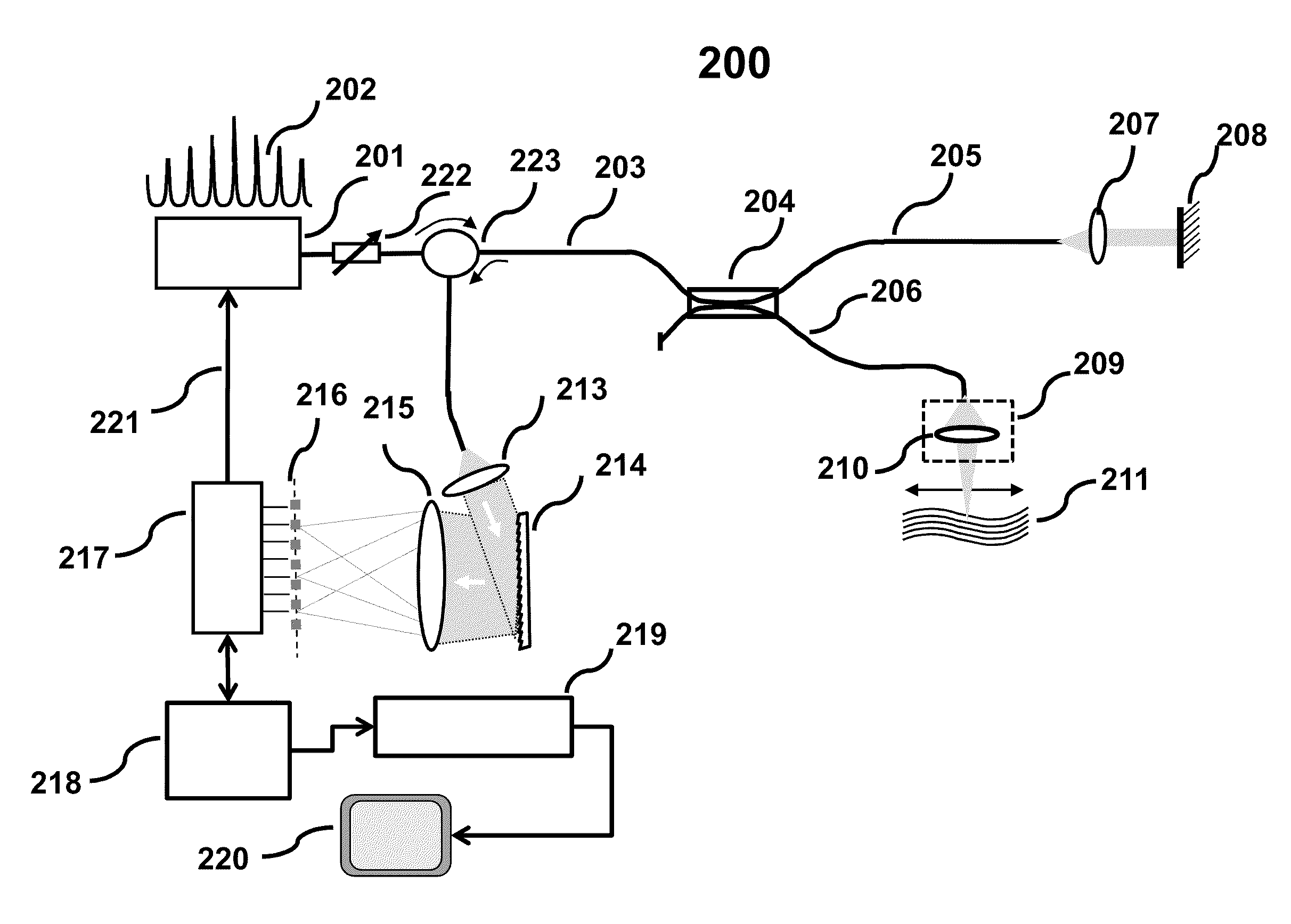
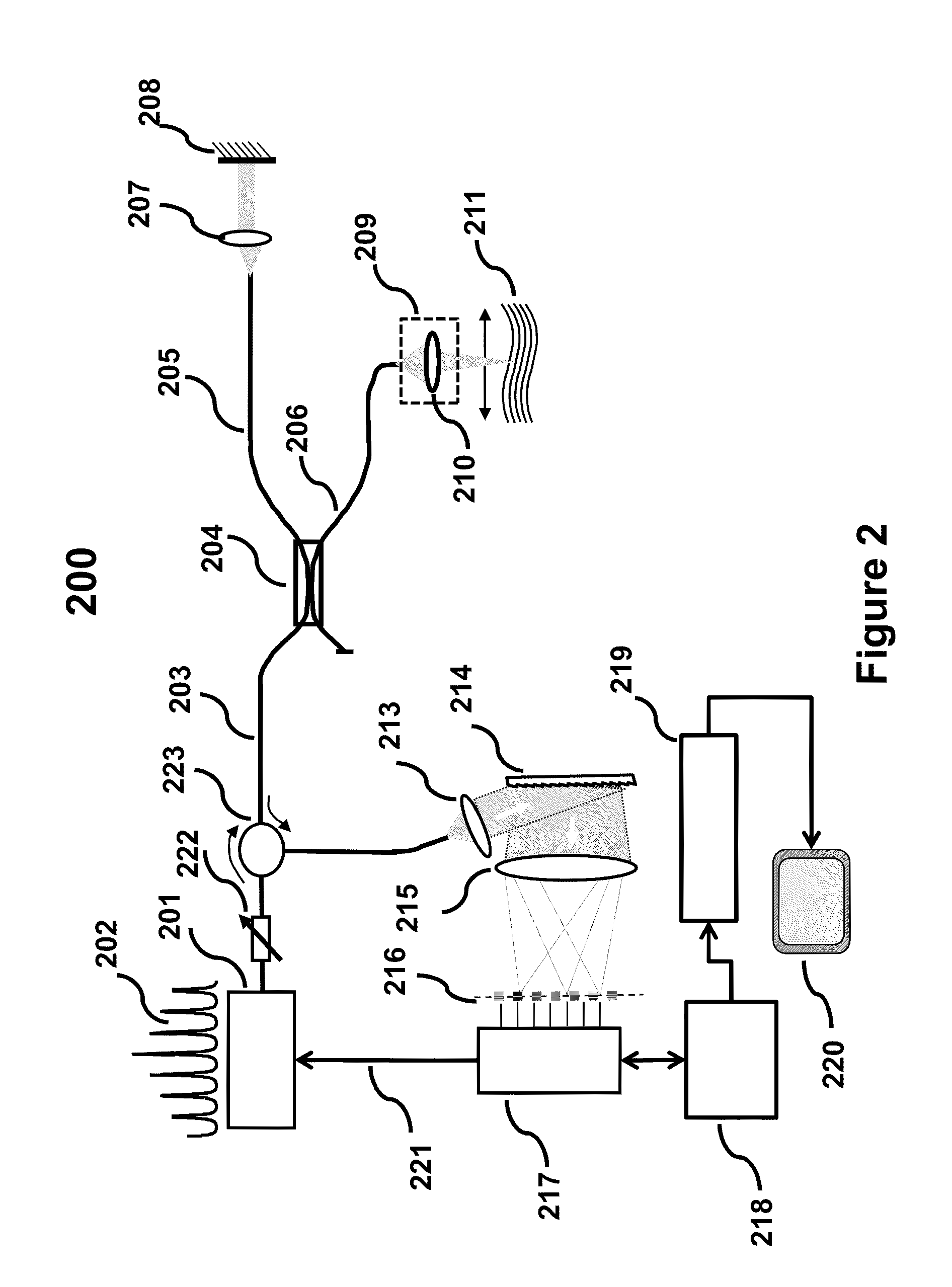
[0021]A new SD-system is provided where input light is provided using a broadband source characterized by a spectral profile comprising a discrete set of individual spectral components such as multiple emission lines having high output peak power. In order to improve the detection sensitivity further, the spatial distribution of the spectral components is designed to match the spatial resolution of detectors in a detector array (detector array pitch) so as to provide high input optical power at each detector simultaneously. Signal from each detector could be read simultaneously or sequentially, at a rate faster than the scanning speed of a tunable laser (typically used in a SS-OCT), thereby achieving higher imaging speed.

Problems solved by technology

While the method is accurate, limitations of a conventional TD-OCT system is well documented in the U.S. Pat. No. 7,697,145 issued to Izatt on Apr. 13, 2010 which is being incorporated by reference in its entirety.
Some of the limitations are, complexity and relatively low speed of mechanical scanning devices, single detector that serially obtains signal to build a sample image pixel by pixel, and low source output power resulting in a need for signal integration at the detector that results in low imaging speed.
However, there are differences in systems cost, complexity, and speed capability.
The speed of imaging is limited by the scanning speed of the tunable laser.
In addition, the swept source is complex and bulky.
However, since currently available SLD and ASE sources exhibit low power density, power per pixel received at the detector is comparatively low which may result in lower sensitivity.
In order to achieve higher sensitivity, a longer signal integration time is required at the detector array thereby, limiting the speed of imaging.

Method used


Image

  • Discrete Spectrum Broadband Optical Source
  • Discrete Spectrum Broadband Optical Source
  • Discrete Spectrum Broadband Optical Source

Examples


Embodiment Construction

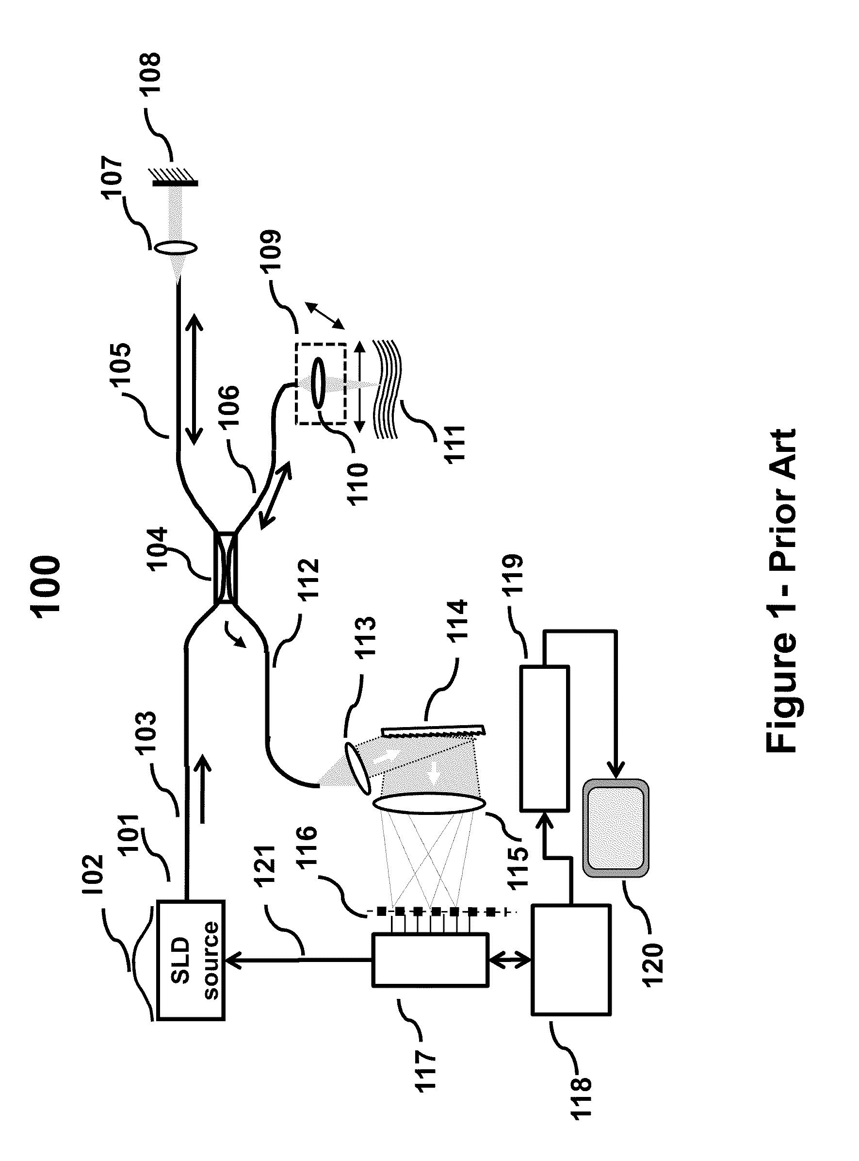
[0032]For clarity and ease of discussion, each drawing figure shows a particular aspect or a combination of few aspects that may be implemented in an embodiment either alone or, in combination with one or more different aspects shown in other embodiments of the invention. Different aspects described in various embodiments may be combined without deviating from the principles of the invention. It is not be construed that an element not shown in any embodiment is precluded from the features shown in that drawing figure unless stated otherwise. Like elements in each drawing figure are represented by similar reference numerals wherever possible (for example reference numeral 201 in FIG. 2 represents an element that is identical or performs equivalent function, referred as 101 in FIG. 1) for ease of understanding, and to avoid repeated explanation.

[0033]Referring now to FIG. 1, there is shown a schematic representation of a prior art SD-OCT system 100 currently used in many medical imagi...


PUM


Abstract

A new broadband source having a discrete set of spectral emission lines having high peak power in each line is provided by placing a gain medium in a reflective cavity comprising reflective front and back surfaces. A cavity feedback factor less than unity is achieved by providing reflectivity of one surface substantially lower than the reflectivity of the other surface such that spontaneous emission in the gain medium is linearly amplified just below the lasing threshold. In an alternative arrangement, a movable external back surface placed at a prescribed distance from the gain medium provides a means to achieve a free spectral range and finesse of the emission lines to match a pitch of a detector array in a SD-OCT system. By simultaneously providing high power to each detector element of the array, sensitivity and imaging speed of SD-OCT system are significantly improved.

Description

CROSS REFERENCE TO RELATED APPLICATION[0001]This application claims priority from the U.S. Provisional Patent Application No. 61 / 396,284 filed on May 26, 2010 under the provision of 35 U.S.C. §119(e).BACKGROUND OF THE INVENTION[0002]1. Field of the Invention[0003]This invention is related to the field of Optical Coherence Tomography (OCT) imaging systems and in particular to a light source with an optical spectrum exhibiting a discrete set of narrow peaks having high optical power, to be used with OCT imaging systems.[0004]2. Description of the Related Arts[0005]Optical Coherence Tomography (OCT) is a fast and accurate optical imaging technique frequently used in producing high-resolution diagnostic images for a variety of diagnostics and clinical applications. Currently, most common commercial application of OCT is primarily in the field of ophthalmology. Emerging applications include but are not limited to, field of cardiology, dentistry, cancer diagnosis, glucose monitoring, and ...

Claims


Application Information

Patent Timeline
Patent Type & Authority Applications(United States)
IPC IPC(8): G01B9/02
CPCH01L33/0045H01S5/0287H01S5/101G01B9/02091G01B9/02044G01B9/02008H01S5/1085
Inventor ALPHONSE, GERARD A
Owner GDAC PHOTONICS INC
Learn More