Classification of interference

a technology of interference and classification, applied in the field of classification of interference, can solve the problems of inability to mitigate interference effects, especially vulnerable passive systems, and detrimental effects, and achieve the effects of reducing multi-user interference, reliable detection, and improving automotive radar

Active Publication Date: 2011-12-01
MITSUBISHI ELECTRIC CORP
View PDF3 Cites 10 Cited by
  • Summary
  • Abstract
  • Description
  • Claims
  • Application Information

AI Technical Summary

Benefits of technology

[0222]In the above example. blanking alone was not sufficient to suppress effects of multiuser interference. However, by using adaptive selection of transmitted frequency sweeps together with signal blanking, reliable detection was achieved.
[0223]However, in alternative scenarios, adaptive selection of transmitted frequency sweeps alone may be su...

Problems solved by technology

There are many known cases of detrimental effects of interference on various active and passive sensing systems.
Passive systems are especially vulnerable because they do not transmit any probing signals so that the interference effects cannot be mitigated by simply increasing the transmitted power.
Unfortunately, the microwave frequency bands utilised for passive remote sensing are also used for communication and surveillance purposes; such applications involve the generation and transmission of high-level microwave signals.
The resulting interference manifests itself as the appearance of ‘hot spots’ that will corrupt images of microwave brightness temperature.
Therefore, a passive energy sensor is not capable of discriminating between man-made interference and interference originated from natural phenomena.
According to the International Telecommunications Union Recommendation (ITU-R RS.1029-2): “studies have established that measurements in absorption bands are extremely vulnerable to interferenc...

Method used


Image

  • Classification of interference
  • Classification of interference
  • Classification of interference

Examples


Embodiment Construction

[0051]Before describing some practical embodiments of the present invention, the underlying theory behind the embodiments is provided.

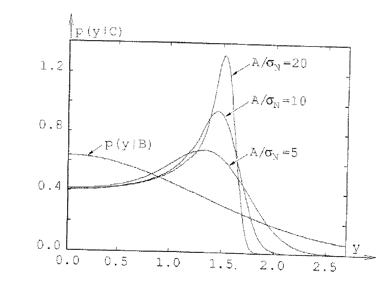
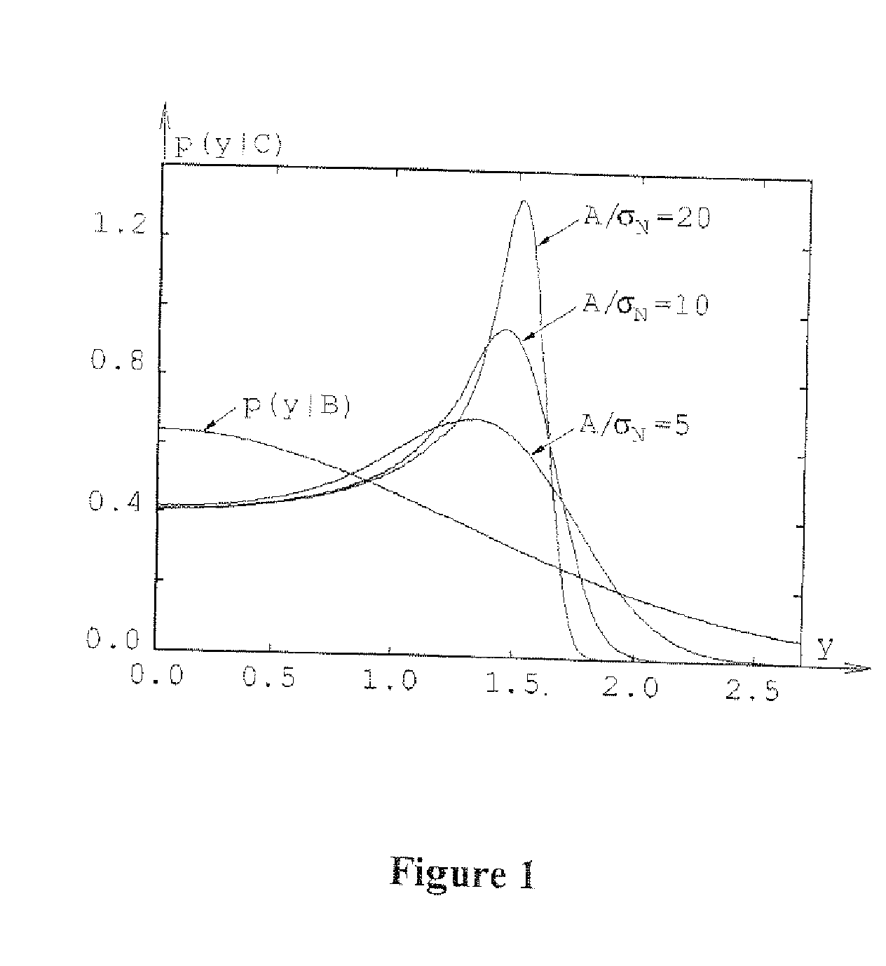
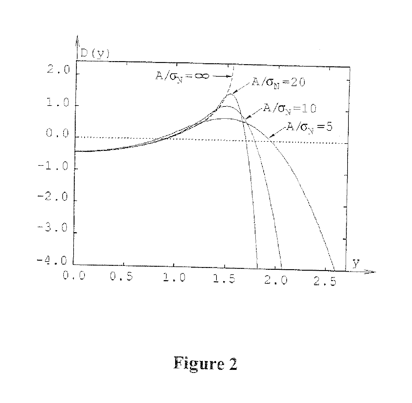
[0052]Consider a received signal that comprises standard background noise (e.g. thermal noise) and pulse-like high-level interference (i.e. transient interference). Such transient interference may have originated either from a short burst of wideband noise or from a pulse with frequency-modulated carrier (a chirp).

[0053]In systems employing discrete-time signal processing, a noise burst will produce a sequence of samples having a Gaussian distribution, whereas a frequency chirp will generate samples with the same characteristics as those obtained by random sampling of a constant-amplitude sinusoidal wave. This observation can be exploited in many different ways to develop a statistical procedure for discriminating between noise bursts and chirps. However, neither duration nor the power of observed transient interference can provide any useful informat...


PUM


Abstract

An interference classifier is disclosed for determining the type of interference present in a signal. The interference classifier 601 comprises a buffer 602 operable to receive and store data comprising samples of a signal; a scale factor calculator 603 operable to use the signal samples to calculate a scale factor in dependence upon the levels of the signal samples; a normaliser 604 operable to calculate normalised signal samples by using the scale factor to normalise the signal samples; a nonlinear transformer 605 operable to perform a nonlinear transform on the normalised signal samples to calculate transformed signal samples; an averaging circuit 606 operable to calculate an average of the transformed signal samples; and a comparator 607 operable to compare the calculated average of the transformed signal samples to a predetermined threshold level in order to determine the type of interference present in the received signal. The interference classifier 601 disclosed herein performs an advantageous type of nonlinear transform that provides an improvement in detection probability over known kurtosis-based interference classifiers. Applications of the interference classifier 601 include automotive radar systems, radio astronomy, microwave radiometry, weather forecasting and cognitive radio networks.

Description

CLAIM TO PRIORITY[0001]The present application claims priority from European patent application number EP 10164050.6 filed on 27 May 2010, the full contents of which are incorporated herein by cross-reference.FIELD OF THE INVENTION[0002]The present invention relates to a method and apparatus for discriminating between transient interference originating from noise bursts and transient interference generated by sinusoidal signals, including frequency-swept waveforms.BACKGROUND OF THE INVENTION[0003]There are many known cases of detrimental effects of interference on various active and passive sensing systems. Passive systems are especially vulnerable because they do not transmit any probing signals so that the interference effects cannot be mitigated by simply increasing the transmitted power.[0004]For example, in radio astronomy at the 1.2-1.4 GHz frequency band, spectroscopy and pulsar observations are corrupted by transmissions of ground-based aviation radars. Since radio telescope...

Claims


Application Information

Patent Timeline
IPC IPC(8): H04B17/00
CPCH04B1/1027
Inventor SZAJNOWSKI, WIESLAW JERZY
Owner MITSUBISHI ELECTRIC CORP
Why Eureka
Try Eureka