
Method and apparatus for the generation, heating and/or compression of plasmoids and/or recovery of energy therefrom

a technology of plasmoids and heating devices, applied in nuclear reactors, nuclear engineering, greenhouse gas reduction, etc., can solve the problems of large change in earth's atmosphere, complex and large physical scale of plasma confinement systems and associated heating systems, and achieve high plasma-to-magnetic energy ratio, low reactor cost, and linear geometry simple

Active Publication Date: 2011-12-01
MSNW
View PDF5 Cites 48 Cited by
  • Summary
  • Abstract
  • Description
  • Claims
  • Application Information

AI Technical Summary

Benefits of technology

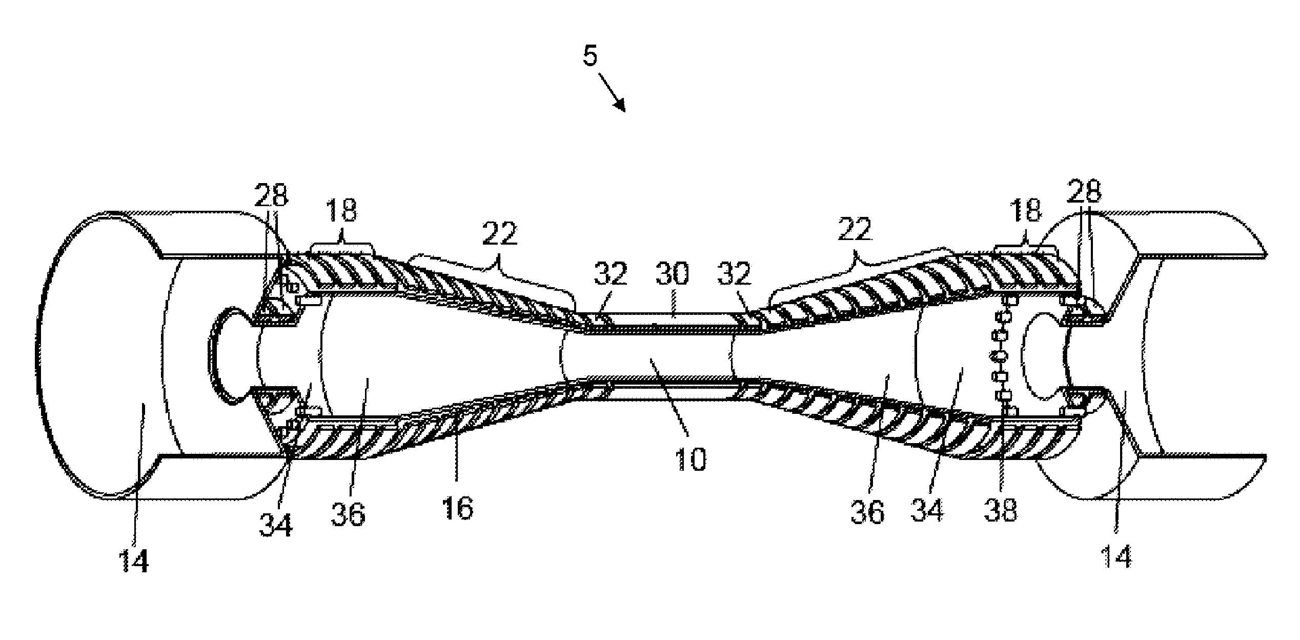
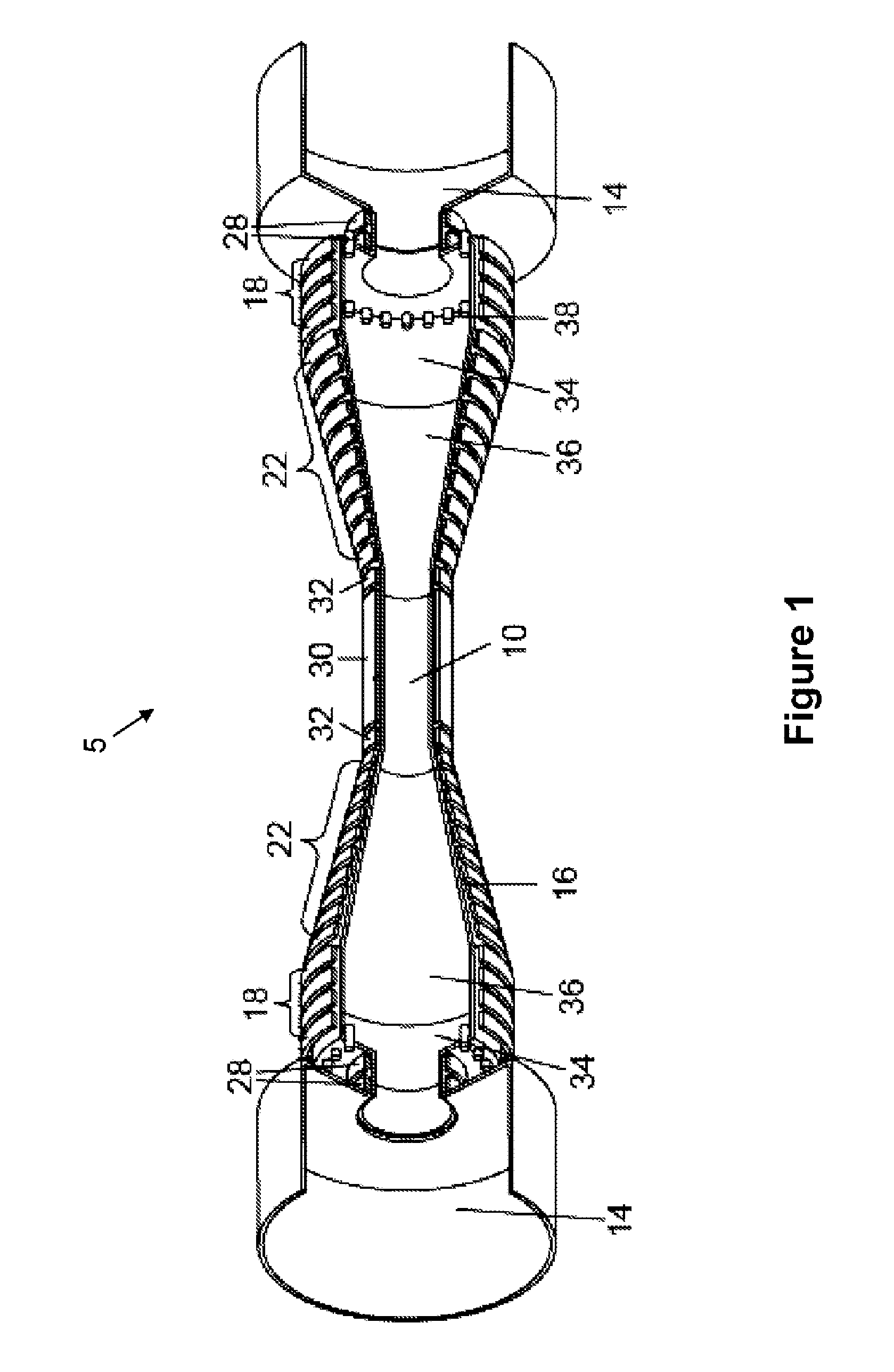
[0012]A quasi-steady fusion reactor based on plasmoids provides for a method to operate at an optimal power density. The methods and apparatus described herein provide a range of other desirable features as a source of neutrons including production of rare isotopes, diagnostic instruments and energy generation. For the generation of energy, many methods incorporate, but are not limited to, i) the generation of energy from fusion using a range of fuel (e.g., deuterium and lithium); ii) the conversion of Thorium to a fissile fuel; and iii) the transmutation of the radioactive waste to energy. These present many possible advantages. For example, the unique ability of the plasmoid to be translated over distances of several meters allows for the formation and kinetic energy input to be added incrementally outside of the interaction chamber and breeding blanket. This avoids the numerous challenges confronting other approaches where the sophisticated devices needed to create, heat, and sustain the plasma must be co-located along with the reactor blanket and power processing systems. Also for example, such may allow plasma exhaust (divertor) region to be well removed from the reactor, eliminating critical power loading issues. The entire high field reactor vacuum magnetic flux is external to plasmoid flux and is therefore divertor flux. In a transient burn, the particle loss from the plasmoid will be overwhelmingly directed to the divertor regions as the axial flow time is many orders of magnitude smaller than the perpendicular particle diffusion time in the open flux region. As another example of the possible advantages, by virtue of the cyclic nature of the burn, virtually all of the fuel can be introduced during the initial formation of the plasmoid with no need for refueling. As yet another example, the ability to locate the divertor remotely in an essentially neutron-free environment makes tasks such as fuel recovery and divertor maintenance much easier to perform. As still another possible advantage, both reactor and divertor wall loading may be easily regulated by the pulse duty cycle. As yet still another possible advantage, due to the linear, cylindrical reactor geometry there can be a high conversion efficiency of the fast fusion neutrons. As even still another possible advantage, the simply connected, linear geometry of the reactor vessel is amenable to a liquid metal wall interface. This would allow for operation at the highest power density, and solve several plasma-material wall issues.
[0051]One advantage of these embodiments is that fusion, plasma and electrical energy are all used efficiently. In yet another embodiment, these advantages are used in a commercial application to provide power at a low cost. Using certain fusion reactions, for example between deuterium and tritium, the fusion reaction produces neutrons that can interact with lithium containing materials in a blanket surrounding a interaction chamber such that the energetic neutrons are absorbed by the lithium and converted into tritium fuel and heat. The heat may be advantageously used to generate electricity, either in a way conventional to a power plant operating on a steam cycle, or in alternative ways. One advantage of this embodiment is that the device produces heat for conventional power generation and at the same time produces more tritium fuel than it consumes.

Problems solved by technology

The tremendous change that has been made to the Earth's atmosphere, and the potential looming climate catastrophe, are a consequence of the fact that energy was obtained by the consumption of staggering quantities of fossil fuels.
However, the entry of fusion as a viable, competitive source of power has been stymied by the challenge of finding an economical way to heat and confine the plasma fuel.
The main challenges to plasma heating and confinement are the complexity and large physical scale of the plasma confinement systems and associated heating systems.
The more massive the system required to confine and heat the fusion plasma, the higher the cost to develop and operate it.
The tokamak embodiment leads to large reactor sizes due to the low ratio of the plasma energy to magnetic energy and the need to operate at steady state (low power density).
In this embodiment, the efficiency and complexity of the fast laser energy delivery systems become the problem, particularly the ability to rapidly and repetitively pulse these lasers to achieve reasonable levels of power efficiency.

Method used


Image

  • Method and apparatus for the generation, heating and/or compression of plasmoids and/or recovery of energy therefrom
  • Method and apparatus for the generation, heating and/or compression of plasmoids and/or recovery of energy therefrom
  • Method and apparatus for the generation, heating and/or compression of plasmoids and/or recovery of energy therefrom

Examples


Embodiment Construction

[0064]In the following description, certain specific details are set forth in order to provide a thorough understanding of various disclosed embodiments. However, one skilled in the relevant art will recognize that embodiments may be practiced without one or more of these specific details, or with other methods, components, materials, etc. In other instances, well-known structures associated with the field reversed configuration have not been shown or described in detail to avoid unnecessarily obscuring descriptions of the embodiments.

[0065]Unless the context requires otherwise, throughout the specification and claims which follow, the word “comprise” and variations thereof, such as, “comprises” and “comprising” are to be construed in an open, inclusive sense that is as “including, but not limited to.”

[0066]Reference throughout this specification to “one embodiment” or “an embodiment” means that a particular feature, structure or characteristic described in connection with the embod...


PUM


Abstract

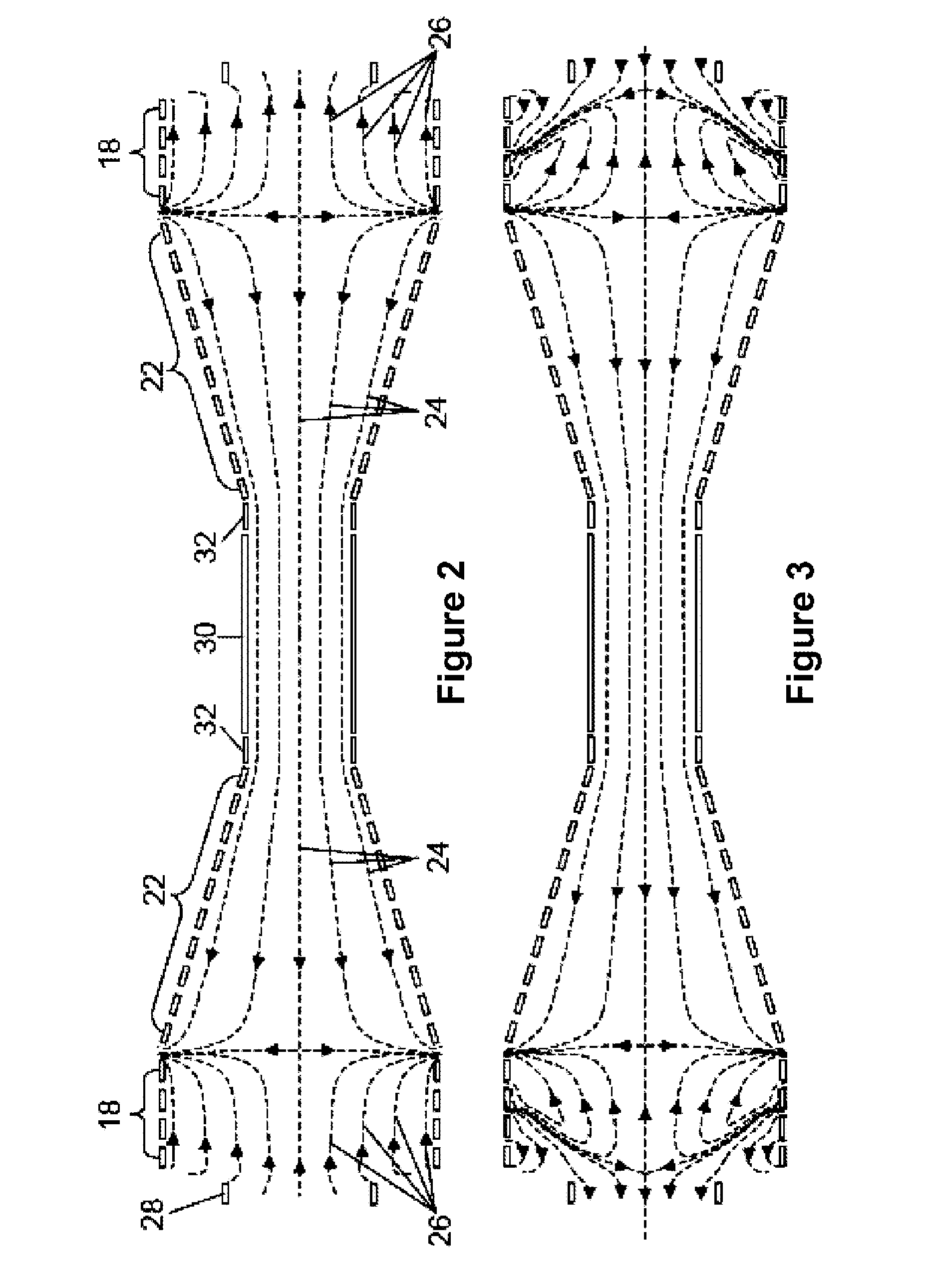
Method and apparatus for heating and / or compressing plasmas to thermonuclear temperatures and densities are provided. In one aspect, at least one of at least two plasmoids separated by a distance is accelerated towards the other. The plasmoids interact, for instance to form a resultant plasmoid, to convert a kinetic energy into a thermal energy. The resultant plasmoid is confined in a high energy density state using a magnetic field. One or more plasmoids may be compressed. Energy may be recovered, for example via a blanket and / or directly via one or more coils that create a magnetic field and / or circuits that control the coils.

Description

CROSS-REFERENCE TO RELATED APPLICATION(S)[0001]This application is a U.S. national stage application filed under 35 U.S.C. §371 of International Patent Application PCT / US2010 / 024172, accorded an international filing date of Feb. 12, 2010, which claims benefit under 35 U.S.C. 119(e) to U.S. provisional patent application Ser. No. 61 / 152,221, filed Feb. 12, 2009, and incorporates by reference the contents of these applications in their entirety.BACKGROUND[0002]1. Technical Field[0003]This disclosure generally relates to the field of plasma physics, and, more particularly, to methods and apparatus for heating and / or compression of plasmoids.[0004]2. Description of the Related Art[0005]There is no question that the world's demand for energy will only increase. The advancement of virtually every modern society parallels the availability of copious, low-cost energy. The tremendous change that has been made to the Earth's atmosphere, and the potential looming climate catastrophe, are a con...

Claims


Application Information

Patent Timeline
Patent Type & Authority Applications(United States)
IPC IPC(8): G21B1/00
CPCG21B1/19Y02E30/122G21B1/052Y02E30/16Y02E30/10H05H1/02
Inventor SLOUGH, JOHN T.
Owner MSNW
Learn More