Method of enriching a gaseous effluent in acid gas

a gaseous effluent and acid gas technology, applied in the field of gaseous effluent enrichment in acid gas, can solve the problems of acid gas capture energy consumption and poor industrial use of the method, and achieve the effect of reducing the energy consumption reducing the operating cost of the acid gas capture method

Inactive Publication Date: 2011-12-01
INST FR DU PETROLE
View PDF3 Cites 5 Cited by
  • Summary
  • Abstract
  • Description
  • Claims
  • Application Information

AI Technical Summary

Problems solved by technology

This method is poorly suited for an industrial use because its energy consumption is hig

Method used


Image

  • Method of enriching a gaseous effluent in acid gas
  • Method of enriching a gaseous effluent in acid gas
  • Method of enriching a gaseous effluent in acid gas

Examples


examples

[0101]The following examples that illustrate the invention should not be considered as limitative.

[0102]Experimental Set-Up and Conditions

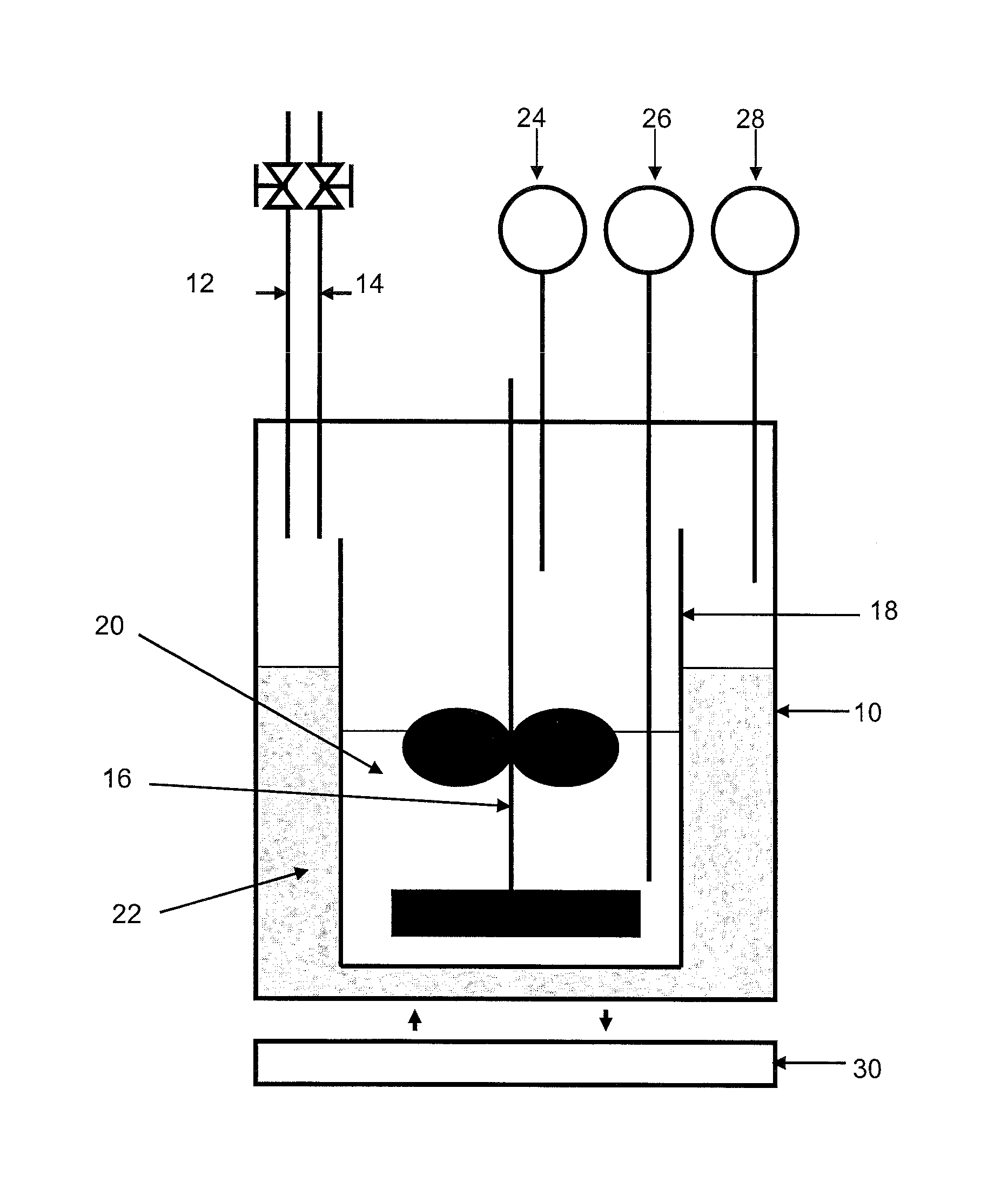
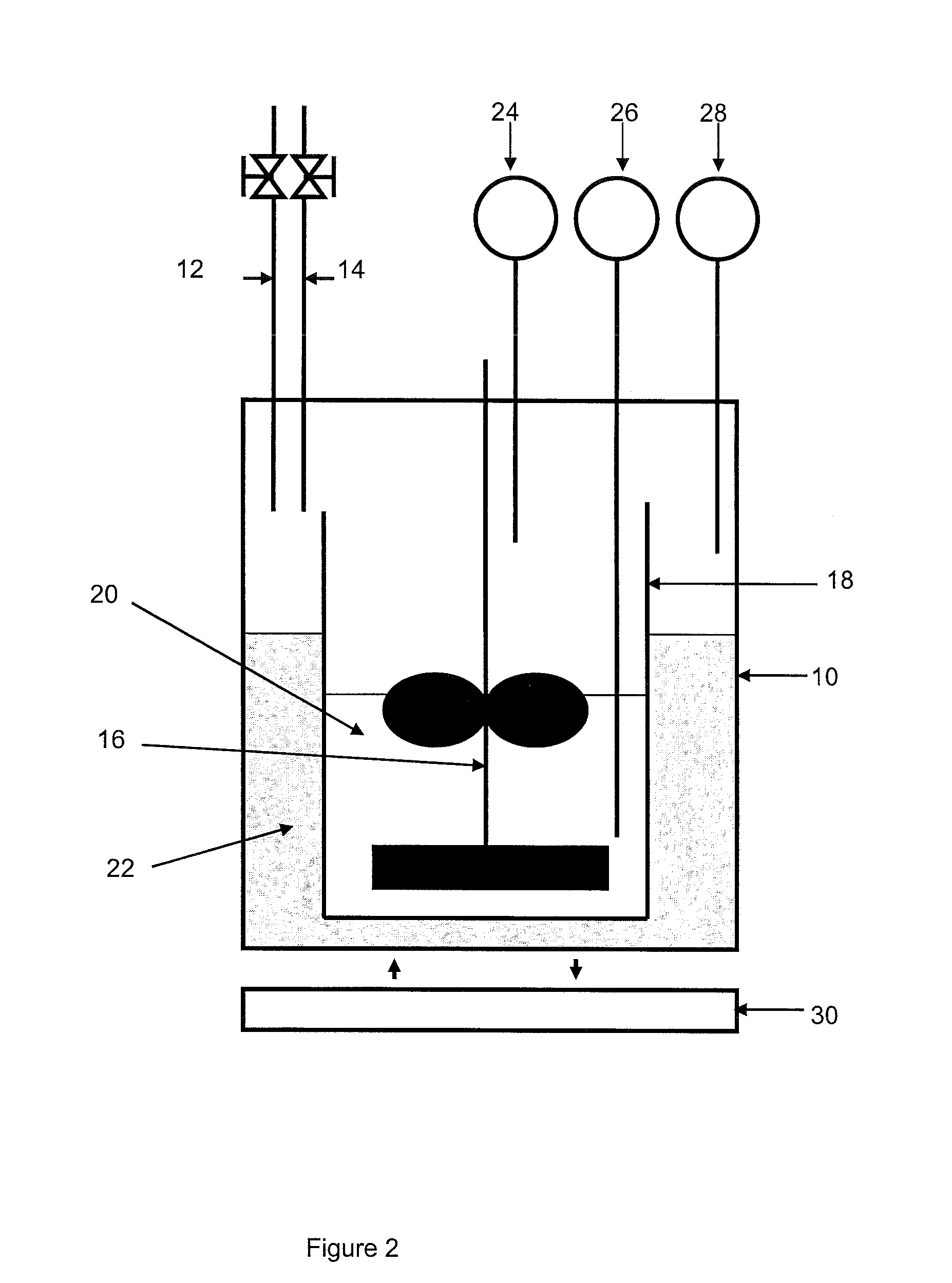
[0103]In order to test the efficiency of the composition used in the method according to the invention, we simulate, in the device in connection with FIG. 2, the hydrate formation stage for a gas mixture containing 85 mole % nitrogen and 15 mole % CO2. The hydrate formation stage is studied in a closed thermostat-controlled reactor wherein the pressure variations of the gas phase and the temperature variations of the gas and liquid phases are measured. These variations are linked with the formation of the hydrates.

[0104]In connection with FIG. 2, the device comprises a 3-liter reactor 10 provided with a gas inlet 12 and a gas outlet 14, a stirring device 16 and temperature and pressure detectors 26, 28, 24.

[0105]The reactor is filled with a mixture 22 of 270 ml milli-Q water and 2 ml ethylene glycol. A glass tank 18 containing 700 ml of the compos...

example no.1 (

Example No. 1 (not in Accordance with the Invention)

[0114]9 mole % tetrahydrofurane (THF) in relation to the aqueous phase are added to the base composition described above. This composition is tested under the aforementioned experimental conditions for three different initial pressure values: 5, 15 and 20 bars.

[0115]The formation of gas hydrates is observed through a pressure drop and the appearance of an exothermic peak when the temperature of the cryostat is decreasing.

[0116]The gas consumption kinetics, therefore the gas hydrate formation kinetics can be modelled by means of a model of a first order reaction. With this composition and at a pressure of 20 bars, the time constant (K) of the hydrate formation reaction is 2 hours. At a pressure of 15 bars, the time constant (K) of the hydrate formation reaction is 3 hours and, at 5 bars, it is 4 hours.

[0117]The final composition of the gas mixture is 9% CO2 and 91% N2.

example no.2 (

Example No. 2 (Not in Accordance with the Invention)

[0118]9 mass % TBAB in relation to the aqueous phase are added to the base composition and this composition is tested under the aforementioned experimental conditions for three different initial pressure values: 5, 15 and 20 bars.

[0119]No exothermic peak and no pressure decrease is observed.

[0120]No hydrate forms under these experimental conditions and in the composition tested.

[0121]The final composition of the gas mixture is identical to the composition of the gas mixture that was injected into the reactor: 85% N2 and 15% CO2.


PUM

PropertyMeasurementUnit
Temperatureaaaaaaaaaa

Abstract

The present invention relates to a method of enriching a gaseous effluent in acid compounds, which comprises the following stages:
    • feeding into a contactor a feed gas comprising acid compounds and a composition comprising at least two liquid phases non-miscible with one another, including an aqueous phase, at least one amphiphilic compound and at least one mixture of promoters,
    • establishing in said contactor predetermined pressure and temperature conditions for the formation of hydrates consisting of water, promoters and acid compounds,
    • carrying the hydrates dispersed in the phase non-miscible in the aqueous phase through pumping to a hydrate dissociation drum,
    • establishing in the drum the hydrate dissociation conditions,
    • discharging the gas resulting from the dissociation enriched in acid compounds in relation to the feed gas.

Description

FIELD OF THE INVENTION[0001]The present invention relates to the sphere of separation of acid compounds such as the hydrogen sulfide (H2S) or the carbon dioxide (CO2) contained in a gas stream, for example natural gas, syngas, fumes or any other industrial effluent. The present invention aims to use a composition comprising a mixture of two liquid phases non-miscible with one another, including an aqueous phase, and a mixture of promoters in a method of separating acid compounds contained in a gaseous effluent so as to increase the efficiency of this method. The invention can be applied to capture the CO2 contained in combustion fumes.BACKGROUND OF THE INVENTION[0002]Gas hydrates are solid crystals that form when gas molecules are in the presence of water under certain pressure and temperature conditions. The water molecules form dodecahedral cages that trap gas molecules such as CO2, H2S, methane, ethane, allowing large amounts of gas to be stored. In general, gas hydrates form nat...

Claims


Application Information

Patent Timeline
IPC IPC(8): B01D53/62C09K3/00C01B32/50
CPCB01D53/1456B01D2252/602B01D53/1493
Inventor SCONDO, ALEXANDRESINQUIN, ANNE
Owner INST FR DU PETROLE
Why Eureka
Try Eureka