Nano-coating thermal barrier and method for making the same

Inactive Publication Date: 2011-12-08
THE BOEING CO
View PDF4 Cites 7 Cited by
  • Summary
  • Abstract
  • Description
  • Claims
  • Application Information

AI Technical Summary

Benefits of technology

[0007]The disclosed thermal barrier coating is light weight and relatively economical to apply over large areas of a substrate. The coating may be tailored to reduce thermal energy transport over a relatively wide range of temperatures, yet is highly durable and is suitable for use in high performance applications, such as those in the aerospace industry. In some applications, use of the disclosed thermal barrier coating may reduce the need for relatively expensive materials such as titanium that may be designed to withstand higher temperatures. In other applications, the coating may also be tailored for lower temperature applications suitable for use on composites such as graphite/epoxy composite materials. The disclosed thermal barrier coating produces phonon interference from any direction of thermal energy flow, in contrast to prior techniques where layered 2-D arrays may reject only tuned phonon frequencies perpendicular to those

Problems solved by technology

In some cases, these internal reflections can be caused to interfere with each other on a quantum level.
This interference results in a highl

Method used


Image

  • Nano-coating thermal barrier and method for making the same
  • Nano-coating thermal barrier and method for making the same
  • Nano-coating thermal barrier and method for making the same

Examples


Embodiment Construction

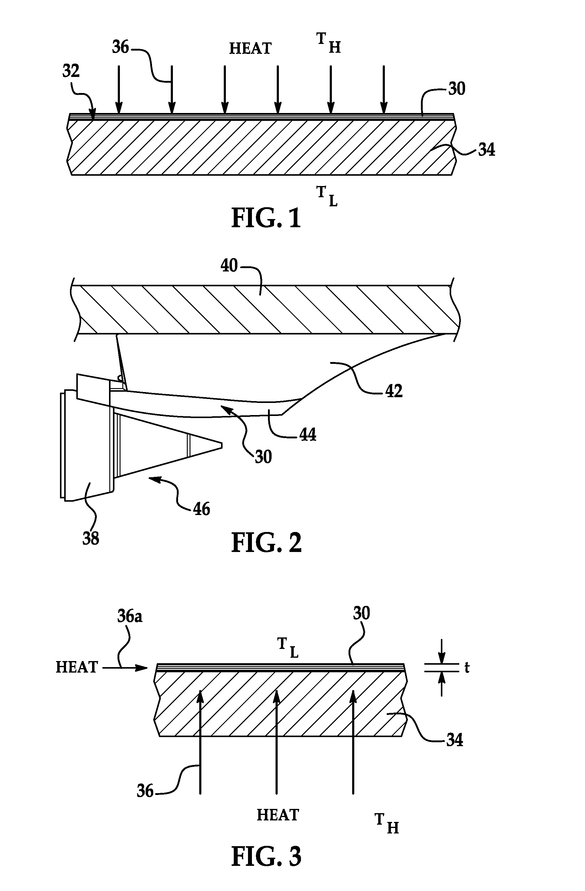
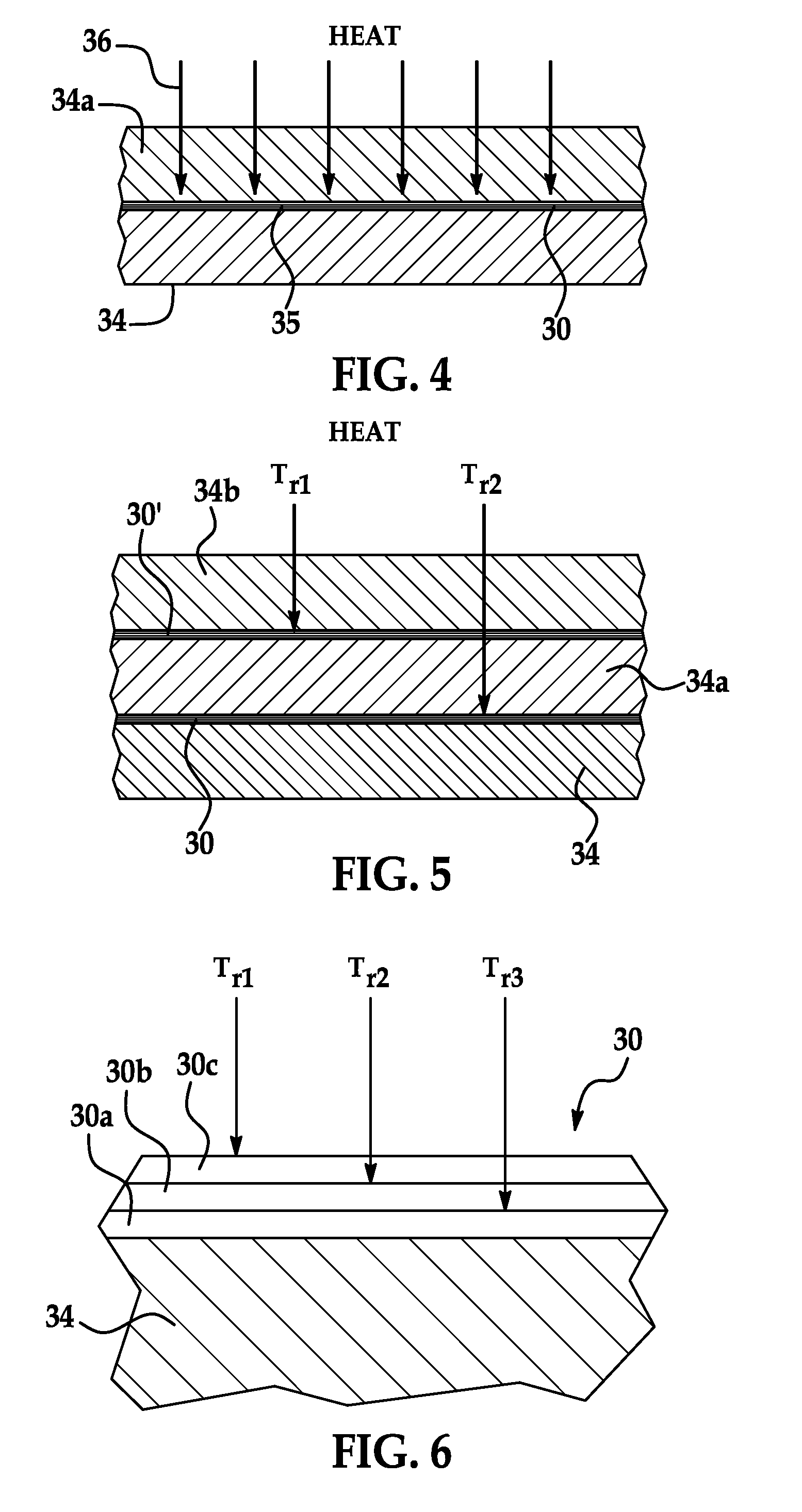
[0029]Referring to FIG. 1, the disclosed embodiments relate to a thermal barrier coating 30 that may be applied to a substrate 34 in order to control the transport of heat 36, also referred to herein as thermal energy, from an area of a higher temperature TH to an area of a lower temperature TL. In the example shown in FIG. 1, the thermal barrier coating 30 is designed to reduce the amount of heat 36 that reaches the substrate 34. As will be discussed below in more detail, the thermal barrier coating 30 may be a relatively thin, durable layer or layers of materials that reduce the transport of thermal energy 36 in the form of thermal quanta known as phonons by interfering with the phonon flow through the coating 30, thus forming a barrier that substantially reduces the thermal energy 36 transferred to the substrate 34. Phonons are quasi-particles characterized by quantization of the modes of lattice vibrations of periodic, elastic crystal structures of solids. Phonons may be viewed ...


PUM

PropertyMeasurementUnit
Temperatureaaaaaaaaaa
Flow rateaaaaaaaaaa
Massaaaaaaaaaa

Abstract

A coating is adapted to be applied to a substrate for managing the flow of heat traveling through the substrate. The coating comprises an array of metal nano-particles held in a glassy matrix.

Description

TECHNICAL FIELD[0001]This disclosure generally relates to techniques for controlling thermal energy transfer through materials, and deals more particularly with a thermal barrier coating and method of making the coating.BACKGROUND[0002]Managing the flow of thermal energy through materials is important in a wide range of industries. Thermal energy flows through a material in the form of thermal quanta known as phonons. The flow of phonons through a material may be reduced by the use of insulation which presents a resistance to the phonon flow, resulting in a thermal differential or temperature gradient. However, the use of insulation to control thermal energy transfer may have limitations in some applications. For example, in the aerospace industry, the use of insulation to reduce thermal energy transfer may add undesired weight to a vehicle or may result in parts that are too large or thick to meet application requirements.[0003]Phonon flow through a material may also be reduced by ...

Claims


Application Information

Patent Timeline
IPC IPC(8): F28F13/18B05D3/02C03C14/00B05D7/00
CPCC03C8/18C04B35/581B22F2998/10Y02T50/67F28F2270/00C04B2235/3895C04B2235/404C04B2235/405C23C24/10C23D5/00C23D5/04F28F2255/06F28F2255/20B22F1/0018B22F1/02B22F1/0074F28F13/185B22F1/054B22F1/16B22F1/107Y02T50/60
Inventor RUSSELL, JAMES C.WHITE, TRESHA L.SHIFLETT, BRYANCHERINET, PAZIONWADLEY, SCOTTBARNHART, CAROLKHOZIKOV, VYACHESLAVNAKAMOTO, KYLE
Owner THE BOEING CO
Why Eureka
Try Eureka