Method of tracking a container using microradios

a container and microradio technology, applied in the field of microradios, can solve the problems of prohibitively large size of miniature radios, relatively long charging time available, and insufficient size, and achieve the effects of less costly, cost effective, and convenient us

Inactive Publication Date: 2011-12-15
RADIOFIDO
View PDF6 Cites 25 Cited by
  • Summary
  • Abstract
  • Description
  • Claims
  • Application Information

AI Technical Summary

Benefits of technology

[0018]Thus, rather than utilizing an RFED tag smart reflector that is able to modulate its reflection, the subject hysteretic switch microradio offers considerable flexibility in its use and makes it possible for very low ambient power to charge the microradio capacitor. When the microradio has enough energy it can be automatically fired off to deliver a relatively large amount of power that can be detected by a distant collector, unlike short-range RFID tags.
[0036]Thus the ability to provide improved microradios in a high-yield process permits applications as diverse as spraying a field for crop health information, or an area to detect a wide variety of terrorist threats. Both consumer and commercial parts of any kind can be sprayed with paint or other coating containing microradios for anti-piracy purposes, as well as to provide for a much more cost effective RFID. Moreover, tracking and other functions are made feasible and inexpensive with the use of the ensemble of microradios provided by the subject technology.

Problems solved by technology

Moreover, the power output of such single microradios leaves something to be desired inasmuch as single microradios are limited in output power, especially when using parasitic powering schemes.
Moreover, in order to parasitically power such miniature radios one needs supercapacitor technology involving high energy density capacitors fabricated in a regular pattern with a large surface area per volume.
It will be appreciated that if the microradio needs to have a given power output to obtain a given range, then the range is severely limited both by the ability to provide supercapacitors or, if a battery is carried on board, then the size of the miniature radio is prohibitively large.
Because batteries cannot be made sufficiently small, one requires that a microradio be powered parasitically, meaning that energy that is available from the environment is captured on a capacitor, where it is rectified and utilized to power the transceiver.
This is due to the relatively long charging time available for the capacitors utilized for each of the microradios versus the short amount of time necessary to transmit information.

Method used


Image

  • Method of tracking a container using microradios
  • Method of tracking a container using microradios
  • Method of tracking a container using microradios

Examples


Embodiment Construction

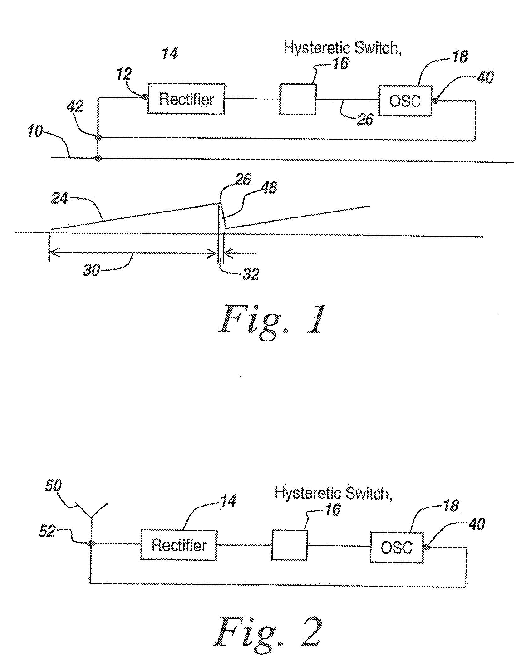
[0083]Referring now to FIG. 1 and prior to discussing applications of microradios, in its simplest configuration the radio is parasitically coupled to the environment through a connection to a metal or dielectric structure that functions as a naturally radiating structure, here illustrated at 10. The microradio has an input 12 coupled to structure 10, at which point a rectifier 14 rectifies RF energy or optical energy to be able to power a radio through a hysteretic switch 16 coupled between the rectifier and an oscillator 18. As will be described, oscillator 18 will transmit an information-bearing waveform. A variety of analog and digital modulations may be employed, including frequency modulation (FM), amplitude modulation (AM), binary phase shift key (BPSK) and binary frequency shift key (BFSK), among other possibilities.

[0084]It is the purpose of hysteretic switch 16 to toggle the power from rectifier 14 to oscillator 18. In one embodiment, the output of oscillator 18 is an enco...


PUM

PropertyMeasurementUnit
charge timeaaaaaaaaaa
lengthaaaaaaaaaa

Abstract

A microradio is provided with a hysteretic switch to permit an optimum range increasing charging cycle, with the charging cycle being long relative to the transmit cycle. Secondly, an ensemble of microradios permits an n2 power enhancement to increase range with coherent operation. Various multi-frequency techniques are used both for parasitic powering and to isolate powering and transmit cycles. Applications for microradios and specifically for ensembles of microradios include authentication, tracking, fluid flow sensing, identification, terrain surveillance including crop health sensing and detection of improvised explosive devices, biohazard and containment breach detection, and biomedical applications including the use of microradios attached to molecular tags to destroy tagged cells when the microradios are activated. Microradio deployment includes the use of paints or other coatings containing microradios, greases and aerosols. Moreover, specialized antennas, including microcoils, mini dipoles, and staircase coiled structures are disclosed, with the use of nano-devices further reducing the size of the microradios.

Description

RELATED APPLICATIONS[0001]This application claims rights under 35 USC §119(e) from U.S. Patent Application Ser. No. 60 / 645,079 filed Jan. 20, 2005; U.S. Patent Application Ser. No. 60 / 645,221 filed Jan. 20, 2005; U.S. Patent Application Ser. No. 60 / 645,222 filed Jan. 20, 2005; U.S. Patent Application Ser. No. 60 / 645,223 filed Jan. 20, 2005; U.S. Patent Application Ser. No. 60 / 645,224 filed Jan. 20, 2005; U.S. Patent Application Ser. No. 60 / 645,226 filed Jan. 20, 2005; and U.S. Patent Application Ser. No. 60 / 645,227 filed Jan. 20, 2005. This application may also be considered to be related to U.S. Application Ser. No. 60 / 711,217 filed Aug. 25, 2005; U.S. Application 60 / 711,314 filed Aug. 25, 2005; U.S. Application 60 / 711,218 filed Aug. 25, 2005; U.S. Application 60 / 711,325 filed Aug. 25, 2005; U.S. Application 60 / 722,309 filed Sep. 30, 2005; U.S. Application 60 / 726,145 filed Oct. 13, 2005; and U.S. Application 60 / 726,146 filed Oct. 13, 2005FIELD OF THE INVENTION[0002]This invention r...

Claims


Application Information

Patent Timeline
Patent Type & Authority Applications(United States)
IPC IPC(8): G06K7/01
CPCH01L23/3114H01Q1/362H01Q7/00H01Q9/27Y10T29/49016H01L2924/0002Y10T29/49124H01L2924/00
Inventor BROMMER, KARL D.BROMMER, TRACEY H.
Owner RADIOFIDO
Why Eureka
Try Eureka