Mask construction for cardiac subtraction

a mask and cardiac subtraction technology, applied in the field of perfusion procedures in digital subtraction angiography, can solve the problems of sensitivity to motion that could have occurred between the current injected frame and the corresponding mask frame, and the so-called residual motion due to heartbeat or respiration is a serious disadvantage of the techniqu

Active Publication Date: 2011-12-15
KONINKLIJKE PHILIPS ELECTRONICS NV
View PDF0 Cites 14 Cited by
  • Summary
  • Abstract
  • Description
  • Claims
  • Application Information

AI Technical Summary

Benefits of technology

[0004]The object of the invention is to provide an improved method for achieving DSA images in which the effect of residual motions during the perfusion phase is reduced in order to display subtracted images containing less motion artefacts.
[0008]In another preferred embodiment the first phase is an arterial phase of the contrast phase, the second phase is a perfusion phase of the contrast phase and the phase dividing time limit is a coronary time limit. Preferably the arterial phase limit is defined by means of image-based criteria. Usually, in perfusion the contrast medium first enters the vessels to be examined in a rather well-defined spatial region. This phase is known as the arterial phase of the contrast injection. When the perfusion progresses the contrast medium migrates towards the myocardiac muscle, yielding a larger and more diffuse spatial region which exists for a further time period. This phase is called the perfusion phase of the contrast injection. Performing the process according to these phases has the advantage that the first subtracted DSA images contain only the coronary arteries and it is unlikely that any serious artefacts are present in these images. Since little time has passed between the end of the mask acquisition and the acquisition of the first contrast images, approximately 0 to 4 seconds, little residual motion is present on these images. It is therefore easy to compensate for those slight discrepancies. Additionally, the contrast medium trajectory is well-defined during the arterial phase. This is not the case during the perfusion phase. Hence, the images generated in the first phase produce easily identified objects. As a result, at that point it is often easier to compensate for artefacts than during the perfusion phase. This leads to mostly artefact-free subtraction images.
[0009]In a preferred embodiment the extended mask image sequence is chronologically closer to the second contrast image than the mask image sequence. With regard to common investigation timing a method is preferred wherein the extended mask image sequence is 2 to 4 seconds closer to the second contrast image than the mask image sequence. The gain in the mask-to-current-image time results in a major reduction of the extent of the potential residual motions (and for the corresponding reduction of transparency artefacts), yielding a much better subtraction quality. Of course the invention is compatible with any existing cardiac DSA method and also any motion compensation technique.
[0010]Preferably, in one embodiment the determination of the introduced phases (arterial and perfusion phases) is automatically determined and does not require patient specific settings. There is a variety of ways to achieve this goal. One might rely on fixed time values, or fixed number of heart cycles (or the combination of both), or even on image-based detection. In addition, the use of an electronic and programmable contrast-agent injector might facilitate this determination (for instance the injection might accurately start after a programmed time period following the sequence acquisition start). One might also use a combination of those methods. For instance, the arterial phase can be automatically detected by digitally monitoring the contrast in the image content, and the perfusion phase can be set with a fixed time interval (or a fixed number of heart cycles, or a fixed combination of both) separating it from the automatically detected arterial phase start).

Problems solved by technology

But it has shown, that motion of the object between the acquisition of the first and the second image leads to disturbing artefacts in the DSA image, as background structures can only be completely eliminated where these structures are exactly aligned and have equal grey-level distributions.
Its sensitivity to motion that could have occurred between the current injected frame and the corresponding mask frame (the so-called residual motion, due to heartbeat or respiration for example) is a serious disadvantage of the technique.
However, it is impossible to clarify myocardial perfusion (which is the ultimate goal of the exam) from the coronary shape.
But residual motions observed in cardiac DSA appear more often, with larger amplitudes, and they are more difficult to compensate for (compared to non-cardiac DSA).
It is then difficult to find a matching pair of images to apply subtraction.
Further, breathing could also impair the mask / injected frame matching and it is more difficult to hold its breath during an exam than to simply stay motionless.
That makes the estimation and compensation of the organs that they contain particularly difficult.
As a result, it is much more difficult to compensate for residual motions in cardiac DSA than in non-cardiac DSA.

Method used


Image

  • Mask construction for cardiac subtraction
  • Mask construction for cardiac subtraction
  • Mask construction for cardiac subtraction

Examples


Embodiment Construction

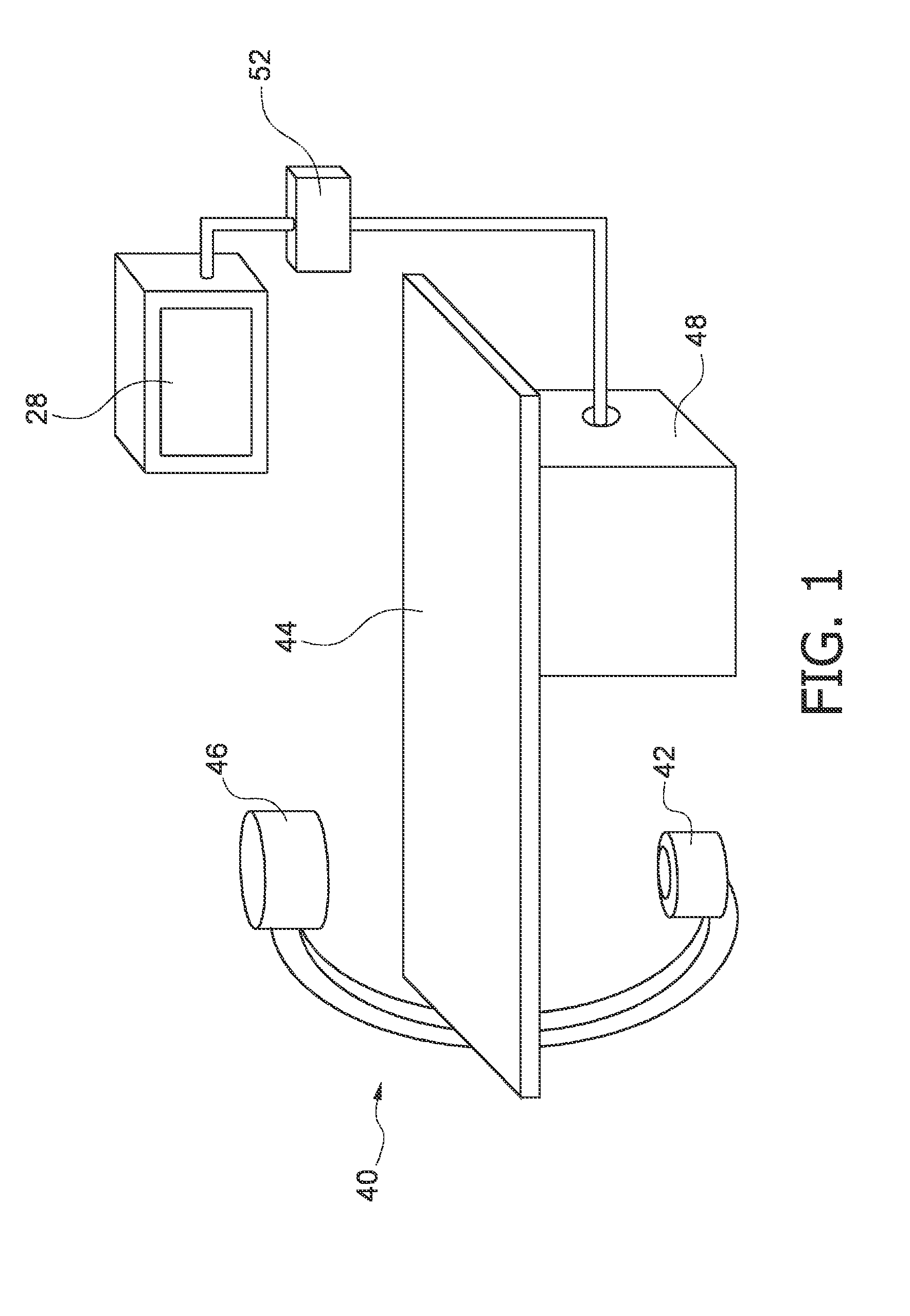
[0026]FIG. 1 schematically shows an X-ray imaging system 40. A source of X-ray radiation 42 is provided to generate X-ray radiation. A table 44 is provided to receive a subject to be examined. Further, an X-ray image detection module 46 is located opposite the source of X-ray radiation 42, i.e. during the radiation procedure, the subject is located between the source of X-ray radiation 42 and the detection module 46. The latter is sending data to a data processing unit 48, which is connected to both the detection module 46 and the radiation source 42. Furthermore a display 28 is arranged in the vicinity of the table 44 to display information to the person operating the X-ray imaging system, i.e. a clinician. Preferably the display 28 is movably mounted to allow for an individual adjustment depending on the examination situation. Also, an interface unit 52 is arranged to input information by the user. Basically, the image detection module 46 generates images by exposing the subject t...


PUM


Abstract

To provide an improved method for achieving DSA images where the effect of residual motions in cardiac DSA during the perfusion phase is reduced and in order to display subtracted images containing less motion artefacts, a method of performing digital subtraction angiography DSA in an imaging apparatus comprises the steps of generating a first image sequence of mask images (10) of a subject to be examined, generating at least one first contrast image (22) at a first phase (16) whereby in the first contrast image part of the subject has a different contrast than in said first image sequence, subtracting the mask images (10) from the at least one first contrast image (22) generating a first DSA image sequence (24), subtracting the DSA images of the first DSA image sequence (24) from the first contrast image (22) within the first phase (16) generating a sequence of extended mask images (32); generating a second contrast image (34) with the imaging system at a second phase (18), said second phase (18) being separated from the first phase (16) by a predetermined phase dividing time limit (20), subtracting the images of the sequence of the extended mask images (32) from the second contrast image (34) generating a second DSA image sequence (38), displaying the second DSA image sequence (38) on a display (28).

Description

FIELD OF THE INVENTION[0001]The invention is related to perfusion procedures in Digital Subtraction Angiography (DSA), especially in cardiac DSA. The invention also relates to an imaging system performing DSA, to a computer program element and to a computer-readable medium.BACKGROUND OF THE INVENTION[0002]For some examinations of the human body it is of great advantage to image only the blood vessels. One known method for this is subtraction angiography, which is based on a perfusion procedure. Basically, a first and a second image are acquired of a region of interest. Between the two images a contrast medium is introduced into the blood vessel, which absorbs X-rays. After the contrast agent is injected an X-ray imaging device records an angiographic sequence that shows the blood vessels containing the contrast agent highlighted in the X-ray image. In order to make the vessel, and especially in heart investigations the myocardial information, more accessible to the clinician, its vi...

Claims


Application Information

Patent Timeline
Patent Type & Authority Applications(United States)
IPC IPC(8): G06K9/00
CPCA61B6/481A61B6/504A61B6/484A61B6/507A61B6/5264
Inventor FLORENT, RAOULAUVRAY, VINCENT MAURICE ANDREBONNEFOUS, ODILE
Owner KONINKLIJKE PHILIPS ELECTRONICS NV
Why Eureka
Try Eureka