Pressure Control System And Method

Active Publication Date: 2011-12-29
WESTPORT FUEL SYST CANADA INC
View PDF8 Cites 99 Cited by
  • Summary
  • Abstract
  • Description
  • Claims
  • Application Information

AI Technical Summary

Benefits of technology

[0040]An advantage of the disclosed system and method is that it can prevent freezing of the flow controllers because these flow controllers are placed downstream of the heater so that the fluid is warmed and converted into a gas before it circulates therethrough. By closing the flow controller on the first conduit, the system ca

Problems solved by technology

A problem with known storage tanks that store cryogenic fluids is that heat leak into the storage space can cause vaporization of some of the stored liquefied gas causing the pressure within the tank to rise above the relief pressure set point, reducing the time that liquefied gases can be held within the tank without venting to relieve the pressure.
This results in a loss of the stored fluid, instead of the lost fluid being delivered to the use device.
This system allows a relatively fast drop in pressure in the tank when needed, although it does present the disadvantage that the predetermined value of the tank pressure which triggers the opening of the regulator in the economizer circuit can not be adjusted.
Another disa

Method used


Image

  • Pressure Control System And Method
  • Pressure Control System And Method
  • Pressure Control System And Method

Examples


Embodiment Construction

)

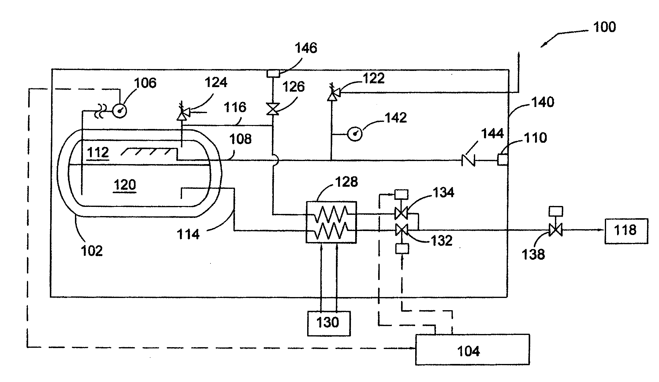
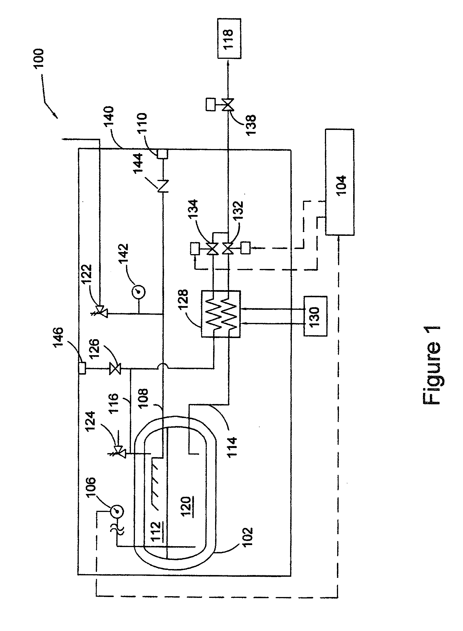
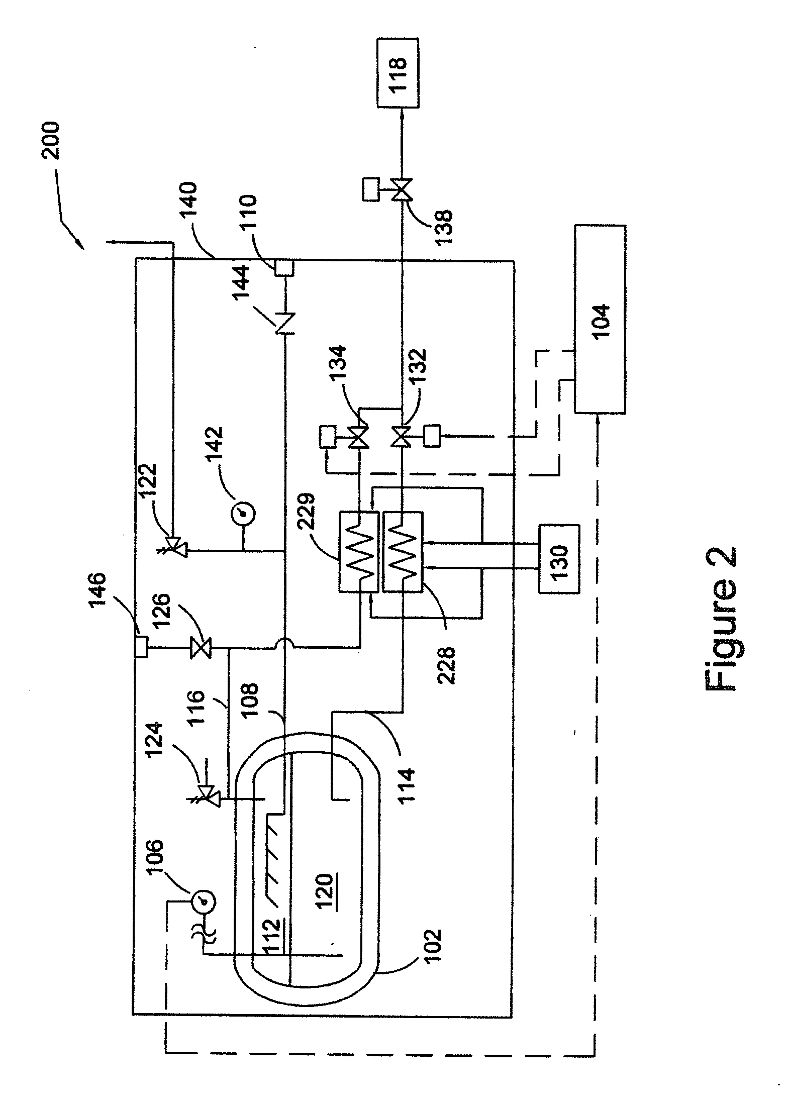
[0044]The illustrated embodiments show an automatic tank pressure control that maintains the pressure inside the tank between predetermined values by actuating the flow controllers disposed on the liquid and vapor conduits based on the signal received from a pressure sensor that measures the pressure inside the pressurized tank. In one preferred embodiment the liquid and the vapor conduits both pass through the same heater and in another preferred embodiment each conduit passes through a separate heater. The heater can be for example an electrical heater, a heat-exchanger or a vaporizer. In the preferred embodiments where both liquid and vapor conduits pass through the same heater, the heater can be a multi-line heat exchanger or vaporizer, and in other preferred embodiments where each conduit passes through a separate heater, the heater can be a single-line heat exchanger or vaporizer. In yet another preferred embodiment, only the liquid conduit passes through a single-line heat e...


PUM


Abstract

A pressure control system comprises separate conduits for supplying liquefied gas and vapor from a cryogen space defined by a cryogenic storage tank. A first conduit can deliver liquefied gas to a use device through a heater and then a first flow controller. A second conduit can deliver vapor to the use device with flow therethrough controlled by a second flow controller. The first flow controller is not exposed to liquefied gas at cryogenic temperatures because it is located downstream from the heater. For automatic operation a pressure sensor measures pressure inside the cryogen space and the first and second flow controllers are independently operable to maintain the pressure inside the cryogen space within a predetermined range. In a preferred embodiment the liquefied gas is a combustible fuel that is consumed by an internal combustion engine, which is the use device.

Description

CROSS-REFERENCE TO RELATED APPLICATION(S)[0001]This application is a continuation of International Application No. PCT / CA2010 / 000212, having an international filing date of Feb. 16, 2010, entitled “Pressure Control System And Method”. The '212 international application claimed priority benefits, in turn, from Canadian Patent Application No. 2,653,643 filed Feb. 26, 2009. The '212 international application is hereby incorporated by reference herein in its entirety.FIELD OF THE INVENTION[0002]The present invention relates to a system and a method for automatically controlling the pressure inside a tank for storing fluids at cryogenic temperatures and preventing the freezing of valves placed on fuel delivery lines that connect the tank with a use device.BACKGROUND OF THE INVENTION[0003]Fluids at cryogenic temperatures, also referred to herein as “cryogenic fluids”, include liquefied gases that can have boiling points below −100° C. (about −150° F.) at atmospheric pressure. Examples of ...

Claims


Application Information

Patent Timeline
IPC IPC(8): F17C9/02F17C13/02
CPCF02M21/06F02D19/027F17C9/02F17C13/025F17C2221/011F17C2221/012F17C2221/013F17C2221/014F17C2221/033F17C2223/0161F17C2223/033F17C2223/043F17C2223/046F17C2225/033F17C2225/044F17C2227/0107F17C2227/0309F17C2227/039F17C2227/0393F17C2250/032F17C2250/043F17C2250/0626F17C2265/031F17C2265/036F17C2265/066Y02E60/321Y02T10/32F02M21/0215F02M21/0221F02M21/0287F02D19/022F17C9/00Y02E60/32Y02T10/30
Inventor BROOK, THOMASLEBLANC, VALERIE
Owner WESTPORT FUEL SYST CANADA INC
Why Eureka
Try Eureka