Unlock instant, AI-driven research and patent intelligence for your innovation.

Wavelength-classifying type x-ray diffraction device

Inactive Publication Date: 2011-12-29
RIGAKU CORP
View PDF2 Cites 15 Cited by
  • Summary
  • Abstract
  • Description
  • Claims
  • Application Information

AI Technical Summary

Benefits of technology

[0024]With the foregoing in view, it is an object of the present invention to enable measurement data based on X-rays of different wavelengths in an X-ray diffraction device to be acquired simultaneously through just one measurement, and thereby to prevent waste of energy and wear of the target within a short time, as well as to enable measurement data based on X-rays of different wavelengths to be acquired in a short time.
[0025]Yet another object of the present invention is to make possible acquisition of diffracted X-ray data of different wavelengths using the entire region of the light-receiving face of a one-dimensional X-ray detector or a two-dimensional X-ray detector, so that highly reliable diffracted X-ray data may be obtained.
[0027]In a known semiconductor X-ray detector according to Japanese Patent Laid Open Publication No. 2010-038722, which is adapted to output an electrical signal upon receiving an X-ray, the semiconductor X-ray detector has a function of outputting an electrical signal depending on the energy of the received X-ray (namely, the wavelength of the X-ray) (herein also referred to as energy resolution). This detector also has a function of discriminating, namely, sorting, the X-rays on the basis of the amount of energy from an upper limit value and a lower limit value of the value of pulse height, and through this discrimination function is able to eliminate the background component in a diffracted X-ray profile.
[0031]In the wavelength-classifying type X-ray diffraction device according to the present invention, a diffracted X-ray beam containing diffracted X-rays of different wavelengths is detected by a pixel array detector in which every pixel is given a wavelength classifying function, and therefore despite the presence of a combination of diffracted X-rays of different wavelengths in the diffracted X-ray beam, diffracted X-rays may be detected and classified according every wavelength. Because of this, measurement data based on X-rays of different wavelengths can be acquired simultaneously and classified through just one measurement. In so doing, waste of energy can be prevented, wear of the target within a short time can be prevented, and measurement data based on X-rays of different wavelengths can be acquired in a short time. Because measurements are completed within a short time, measurements can be carried out without problems, even on substances which are unable to maintain crystal structure for extended periods.
[0032]Moreover, in the wavelength-classifying type X-ray diffraction device according to the present invention, rather than dividing the two-dimensional receiving surface of the X-ray detector and receiving diffracted X-rays of different wavelengths in each of these divided regions, diffracted X-rays of different wavelengths are instead respectively received over the entire region of the receiving surface of the X-ray detector, and therefore data of a plurality of diffracted X-rays of different wavelengths can be respectively acquired over a wider range, and highly reliable diffracted X-ray data can be obtained as a result.

Problems solved by technology

However, because the detectors for detecting the diffracted X-rays lack the ability to distinguish between wavelengths, diffracted X-rays cannot be detected simultaneously while distinguishing among them in terms of their wavelengths (namely, in terms of their energies); rather, detection of diffracted X-rays has been carried out through sorting of the source of one specified X-ray wavelength only, and individually measuring each single X-ray wavelength.
For this reason, problems such as waste of energy and accelerated wear of the target are encountered.
Also, measurements made with X-rays of different wavelengths unavoidably have to be carried out in individual time slots, resulting in the problem of extended measuring times.
However, in this invention, there are encountered a number of problems, such as that the detection regions of the upper and lower halves are close to one another with each region having constricted surface area; measuring time is limited by the readout speed of intensity data; and a limited effective dynamic range results in susceptibility to becoming saturated easily.

Method used


Image

  • Wavelength-classifying type x-ray diffraction device
  • Wavelength-classifying type x-ray diffraction device
  • Wavelength-classifying type x-ray diffraction device

Examples


first embodiment

[0061]The embodiments of the wavelength-classifying type X-ray diffraction device according to the present invention are described below. It should be noted that the present invention is not limited to the following embodiment. While the following description makes reference to the drawings, in some instances, constituent elements may be depicted in the drawings at proportions different from the actual ones in order to aid understanding of characteristic portions.

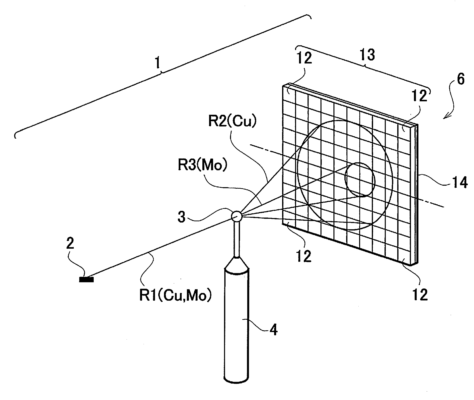
[0062]FIG. 1 shows an embodiment of the wavelength-classifying type X-ray diffraction device according to the present invention. This wavelength-classifying type X-ray diffraction device 1 has an X-ray focal spot 2 provided as X-ray generating means for generating X-rays, a sample support device 4 supporting a sample 3, and an X-ray detector 6 for detecting diffracted X-rays emitted from the sample 3.

[0063]As shown in FIG. 2A for example, the X-ray focal spot 2 is formed as a region where an electron flux emitted from a fil...

second embodiment

[0089]The present embodiment is similar to the first embodiment, but with a modification made to the X-ray generation section.

[0090]As shown in FIG. 2A and FIG. 3A, in the first embodiment described above, the first metal 9a and the second metal 9b are respectively continuous along the direction in which electrons from the filament 7 scan the outside peripheral face of the target 8 (the direction indicated by arrow B), namely, they are provided as ring shapes or annular shapes. Furthermore, the first metal 9a and the second metal 9b are provided adjacent to one another along a direction perpendicular to the direction in which electrons scan the outside peripheral face of the target 8 (a direction parallel to the center line X0 in FIG. 2A).

[0091]By contrast, in the present embodiment, the first metal 9a and the second metal 9b are provided in alternating prescribed widths along the direction in which electrons from the filament 7 scan the outside peripheral face of a target 28 (the d...

modified examples

[0093]The first metal 9a shown in FIGS. 2A, 2B, 3A, and 3B is not limited to Cu. Likewise, the second metal 9b is not limited to Mo. The X-rays of R1, R2, and R3 shown in FIG. 1 are not limited to Cu rays and Mo rays. In FIG. 5, the two comparators 26a, 26b, the counters 27a, 27b, and the counter readout circuit 17 utilize subtraction to classify two wavelengths, i.e., the wavelength indicated by the pulse height V1 and the wavelength indicated by the pulse height V2. However, by instead establishing three or more standard reference voltages, namely, threshold values, the wavelength indicated by the pulse height V1 and the wavelength indicated by the pulse height V2 may be classified directly, without performing a subtraction operation.

[0094]Further, whereas in the embodiment described above, the targets 8, 28 in FIGS. 2A, 2B, 3A, and 3B are provided with two metals 9a, 9b, optionally, the target surfaces may instead be provided with three or more metals, and X-rays of three or more...


PUM


Abstract

A wavelength-classifying type X-ray diffraction device bombards a sample with characteristic X-rays generated from an X-ray generation source, and detects characteristic X-rays diffracted by the sample using an X-ray detector. The X-ray generation source is composed of several metals of different atomic number, respective metals generating several characteristic X-rays of different wavelengths. An X-ray detector is composed of several pixels for receiving X-rays and outputting pulse signals corresponding to X-ray wavelengths. Pixels are respectively furnished with classification circuits. The classification circuits classify and output pixel output signals based on each of characteristic X-ray wavelengths. X-ray intensity is detected on a per-wavelength basis in individual pixels 12. Measurement data based on different wavelength X-rays are acquired simultaneously in just one measurement. Data of diffracted X-rays of different wavelengths are acquired using the entire region of the receiving surface of a two-dimensional detector.

Description

BACKGROUND OF THE INVENTION[0001]1. Field of the Invention[0002]The present invention relates to an X-ray diffraction device of a wavelength-classifying type, having a function whereby X-rays that include a plurality of X-rays of different wavelengths may be classified into X-rays of each of the wavelengths, and X-ray measurements may be carried out using X-rays of the individual wavelengths.[0003]2. Description of the Related Art[0004]In the field of X-ray diffraction devices, there are instances in which it is desired to use a plurality of characteristic X-rays of different wavelengths when measuring a single substance to be measured. For example, for analysis in situations where the wave vector of the X-rays necessitates large radial range (for example, as in radial distribution analysis), or in the case of the multi-wavelength anomalous dispersion (MAD) method used in analyzing the structures of native proteins, there are instances in which a plurality of X-rays of different wav...

Claims


Application Information

Patent Timeline
IPC IPC(8): G01N23/207G01N23/20
CPCG01N23/207H01J2235/086H01J2235/081H01J35/10G01N23/20
Inventor MATSUSHITA, KAZUYUKISAKUMURA, TAKUTOTSUJI, YUJIMAEYAMA, MASATAKAHASEGAWA, KIMIKO
Owner RIGAKU CORP