

Permanent magnet electric machine and permanent magnet for an electric machine
a permanent magnet, electric machine technology, applied in the direction of dynamo-electric machines, magnetic circuit rotating parts, magnetic circuit shape/form/construction, etc., can solve the problems of torque ripple, torque vibration, time-consuming and expensive processing of electric circuits exactly to the intended shap
- Summary
- Abstract
- Description
- Claims
- Application Information
AI Technical Summary
Benefits of technology
Problems solved by technology
Method used
Image

Examples
Embodiment Construction
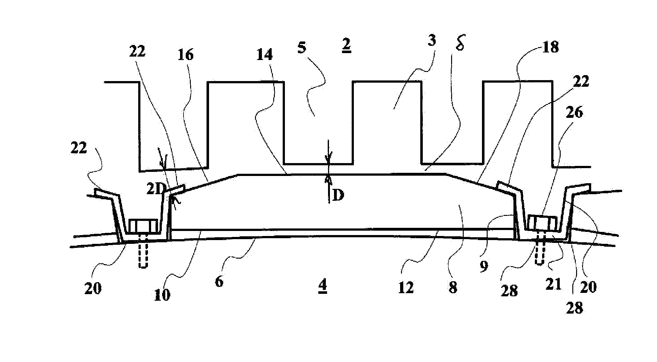
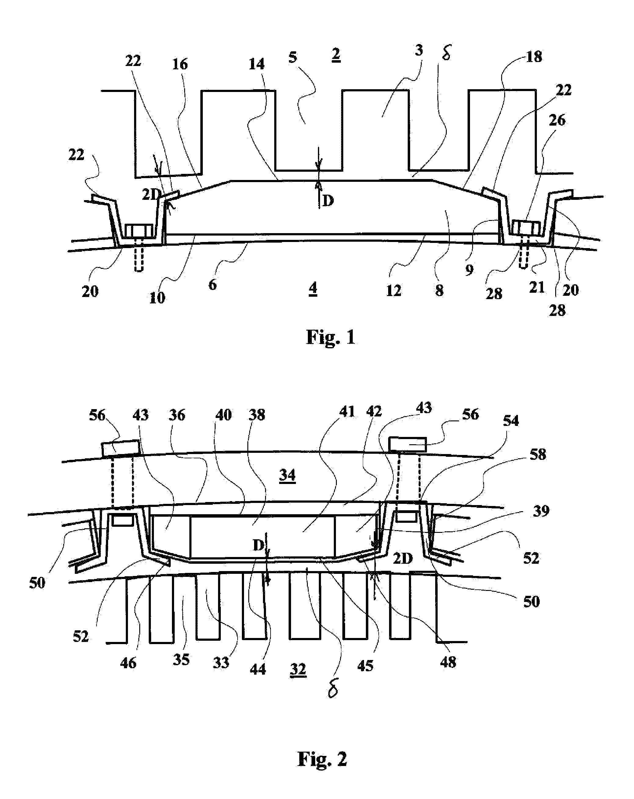
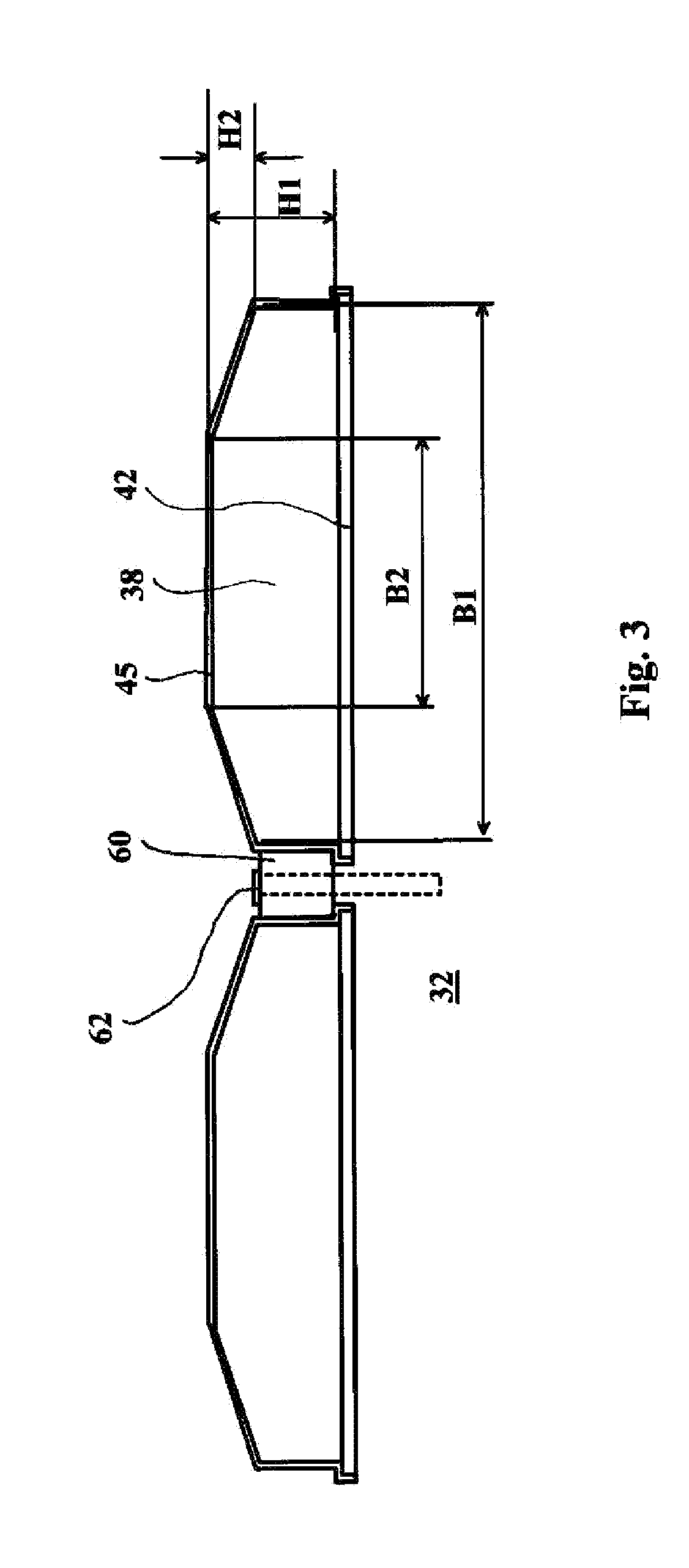
[0021]The disclosure relates to a permanent magnet structure and a permanent magnet rotor which can be inexpensive to manufacture and which can meet electric machine specification both during idling and under load. A method is disclosed for making a permanent magnet electric machine which can simultaneously achieve both a specified sinusoidal distribution of the air gap flow, and an inexpensive manufacturing and finishing of permanent magnets. Ensuring the sinusoidality can be particularly important in multipole electric machines where the winding's number of slots per pole and phase is one or two. In these cases, a harmful impact of slot harmonics is emphasized. It can be technically difficult to manufacture a permanent magnet that is purely sinusoidal with regard to its top surface. Instead, it can be relatively easy to process three straight plane surfaces. The number of work stages does not essentially increase, because the surface of the permanent magnet should in any case be f...
PUM
 Abstract
Description
Claims
Application Information