Optical image acquisition apparatus having adaptive optics and control method for the same
Inactive Publication Date: 2012-01-05
CANON KK
View PDF4 Cites 22 Cited by
Summary
Abstract
Description
Claims
Application Information
AI Technical Summary
This helps you quickly interpret patents by identifying the three key elements:
Problems solved by technology
Method used
Benefits of technology
[0020]The present invention can realize an optical image acquisition apparatus capable of realizing decrease in image acquisition time by using a simple configuration, while securing a high r
Problems solved by technology
However, in the apparatus having a wavefront aberration corrector through a single beam described above, even if a high resolution image can be provided, there is a problem with achieving decrease in image acquisition time.
Because of
Method used
Image
Click on the blue label to locate the original text in one second.
Reading with bidirectional positioning of images and text.
Examples
exemplary embodiment 1
[0147]A first exemplary embodiment describes an example of a configuration with reference to FIG. 7 in which the adaptive optics of the present invention described above is applied to OCT capable of acquiring a three-dimensional optical tomographic image.
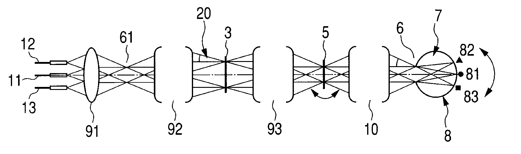
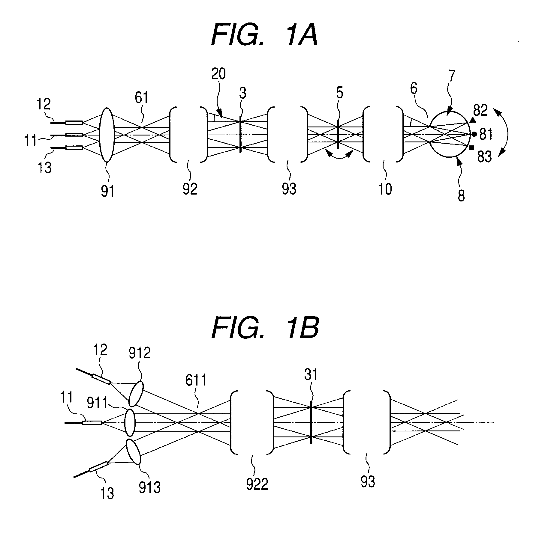
[0148]A beam emitted from a low-coherence light source 100 propagates through an optical fiber and is branched with a predetermined ratio by a fiber combiner, and subsequently is emitted as a divergent beam (measuring beam) from exit ends 11-13, respectively, and then made collimated by collimator optics.
[0149]The three beams made collimated pass through an exit pupil 61, pass through relay optics 92 including a curved mirror, and subsequently enter, in the state of collimated beams with different incident angles, DM3 which is a surface optically conjugate with the pupil 6 in an inspected eye and the exit pupil 61, and then are overlapped on the DM surface with each other. At this time, a beam diameter of each of the beams is φ10 mm...
exemplary embodiment 2
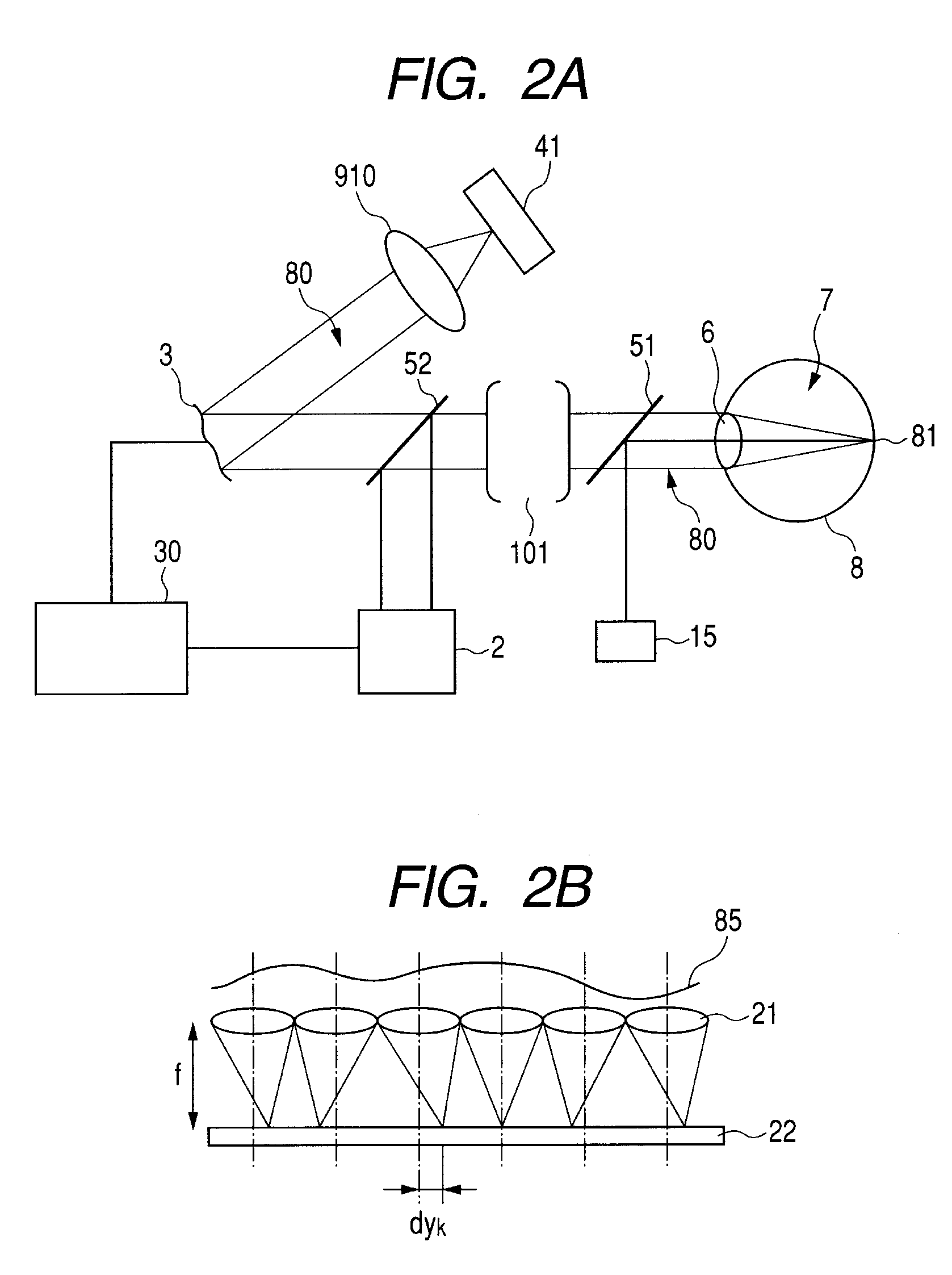
[0168]A second exemplary embodiment describes an example of a configuration in which the adaptive optics of the present invention described above is applied to SLO capable of acquiring a two-dimensional image with reference to FIG. 8.
[0169]Because SLO, different from OCT, does not include an interferometer, SLO is a system in which light intensity of a beam reflected or backscattered by the retina is directly detected by a light intensity detector 160, and thereby a two-dimensional image is provided.
[0170]A configuration including fiber exit ends 11, 12 and 13 to eyepiece optical system 10 may be basically similar to those of the first exemplary embodiment.
[0171]An example in FIG. 8 has also a configuration common to the example in FIG. 7, but before an HS sensor, a beam light blocking unit is not included here, and all beams enter.
[0172]As described with reference to FIG. 5B, beam spacing and a deflection driving angle of a deflector are set so that a scanning range of each of beam...
PUM
Abstract
The present invention provides an optical image acquisition apparatus, while controlling the amount of light within the range prescribed by safety standards, etc., decreasing in image acquisition time by using a simple configuration, as well as securing a high resolution of an optical image by using adaptive optics.
Provided is an optical image acquisition apparatus having adaptive optics, the adaptive optics includes: a wavefront aberration detector for detecting a wavefront aberration in a reflected or backscattered beams generated when a plurality of beams are scanned on a surface, and a single wavefront aberration corrector for correcting a wavefront aberration in each of the plurality of beams, based on the wavefront aberration, and the plurality of beams enter the single wavefront aberration corrector with different incident angles and are overlapped on each other, and the wavefront aberration in each of the plurality of beams is corrected.
Description
TECHNICAL FIELD[0001]The present invention relates to an optical image acquisition apparatus having adaptive optics and a control method for the same, and in particular to a technology by which a two-dimensional or three-dimensional optical image of a tissue in vivo including the retina in the eye which is an object can be acquired in a short time with a high resolution.BACKGROUND ART[0002]A known optical image acquisition apparatus for noninvasively acquiring an optical image of a tissue in vivo as an object such as the retina in the eye includes a Scanning Laser Ophthalmoscope (SLO) capable of acquiring a two-dimensional image, and Optical Coherence Tomography (OCT) capable of imaging a tomographic image of an object.[0003]These apparatuses image and acquire a two-dimensional or three-dimensional optical image, by scanning the retina with a light beam using a deflector and measuring a reflected or backscattered beam. An OCT system includes Time Domain OCT (TD-OCT), Spectrum Domain...
Claims
Application Information
Patent Timeline
Application Date:The date an application was filed.
Publication Date:The date a patent or application was officially published.
First Publication Date:The earliest publication date of a patent with the same application number.
Issue Date:Publication date of the patent grant document.
PCT Entry Date:The Entry date of PCT National Phase.
Estimated Expiry Date:The statutory expiry date of a patent right according to the Patent Law, and it is the longest term of protection that the patent right can achieve without the termination of the patent right due to other reasons(Term extension factor has been taken into account ).
Invalid Date:Actual expiry date is based on effective date or publication date of legal transaction data of invalid patent.