[0036]In accordance with embodiments of the present invention, the present invention is directed to the field of LED light source modules capable of withstanding a harsh environment. More particularly, the present invention relates to a simple LED light
source model that may be efficiently and inexpensively produced and is capable of withstanding the harsh environments in which it is sometimes used. One of the many potential advantages of the methods, devices, and systems of the present invention, only some of which are discussed herein, is that embodiments of the invention provide highly-protective light source modules having a simple structure, low cost for both maintenance and production, easy installation and good generality, and can solve the water protection and heat dissipating problems associated with other existing LED modules. This LED light
source model may be used for outdoor applications since it provides optimal protection from the environment. For the purposes of this disclosure, this model will be referred to as the waterproof model herein. Another
advantage of the present invention includes the a non-waterproof LED light source module which has simple structure, low cost for both maintenance and production, and convenient manufacture that can be done at a large scale. This LED light
source model may be used in indoor applications or in outdoor applications with additional protection from the environment. For the purposes of this disclosure, this model will be referred to as the non-waterproof model. These terms are not intended to be limiting and either embodiment can be used in waterproof or non-waterproof applications, as desired, and / or either embodiment can be modified for use in either an environment calling for a waterproof or non-waterproof device. For example, it may be desired to use the waterproof version in applications where waterproof devices are not a requirement and vice versa. Further, although referred to as a non-waterproof version, such embodiments can be made to be waterproof in other ways, such as with
potting.
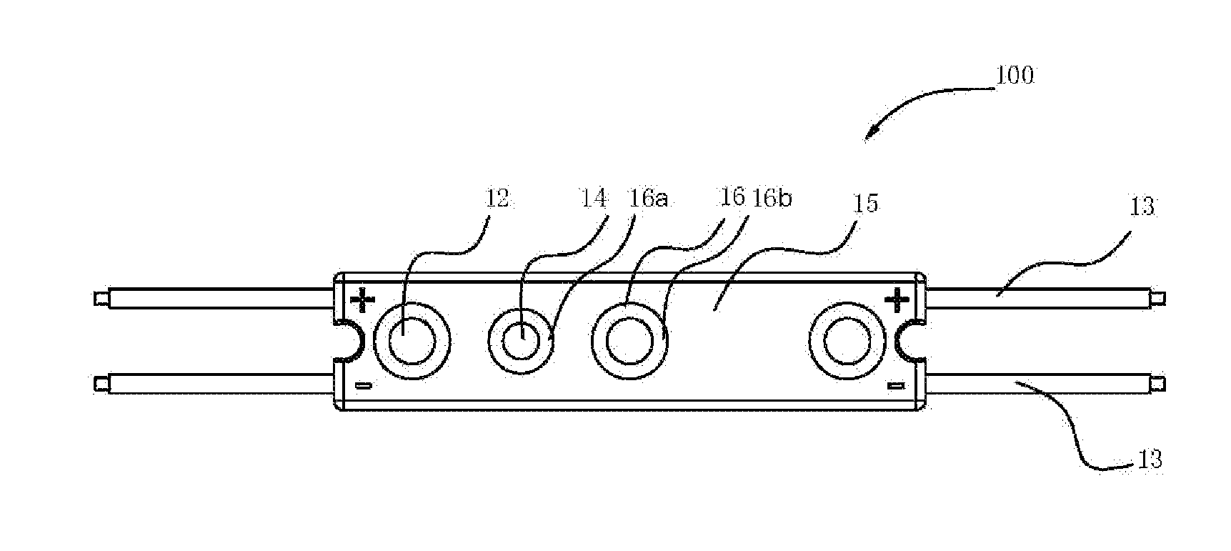
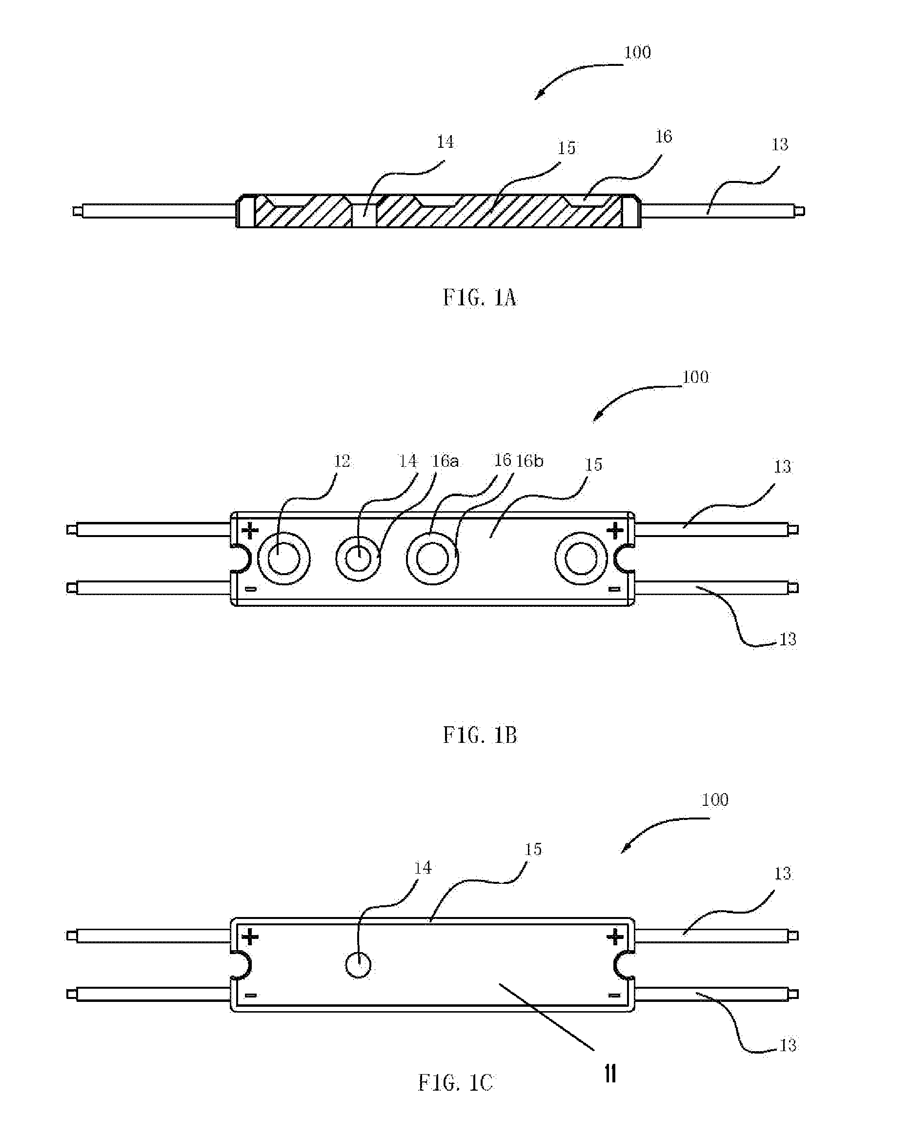
[0037]The waterproof model described herein may comprise a highly-protective heat dissipating LED light source module that further comprises a
metal substrate, at least one light emitting
diode installed on the
metal substrate which is welded with an
electronic component and a power line, and a plastic case formed on the
metal substrate. In certain embodiments, the metal substrate may have an elongated strip shape and may be provided with the power line
welding part on the upper surface (e.g., a
printed circuit board). In an embodiment, the power input line and
power output line may be welded on the two longer sides of the upper surface of the metal substrate respectively. In certain embodiments, the plastic case may be injection molded on the upper surface and periphery of the metal substrate to form a half-encapsulation structure. Alternatively, the plastic cover can be injection molded onto only the upper surface of the substrate circuit board. Indeed, the plastic cover can be injection molded to any and / or all sides or surfaces of the substrate circuit board. Leaving one or more surfaces of the substrate can provide for increased heat dissipation from the device during use.
[0038]The
injection molding process to adhere the plastic cover to the metal substrate can be performed by any known
injection molding process. PVC or ABS
plastic materials may be used to prepare the plastic cover. More specifically, the molding process can include placing the metal substrate and the appropriate die corresponding to the particular configuration of plastic cover desired in a position to enable the plastic material to be formed on the substrate and intended internal components of the LED module (i.e., LEDs, power lines, etc.).
Colloid material is then injected into the die in one or more stages. Pressure is maintained (e.g., between 20-50 MPa for a couple of seconds or longer, such as at 35 MPa for 2.5 s). Then, the
colloid material is allowed to cool for a sufficient period of time to allow for the desired plastic cover to maintain the desired shape and molding quality (for example, about ten seconds or longer, such as 13 s). Prior to molding, it is preferred to bake and mix the
colloid material to achieve a desired characteristic, such as
hardness. For PVC material, the baking can be performed at about 50-90° C., such as about 75° C., for up to about 2 hours. For ABS material, the baking can be performed at about 60-100° C., such as about 85° C. for up to about 4 hours. Once injection molded onto the substrate, the fused plastic cover and metal substrate form a housing capable of protecting the internal components of the housing (e.g., the LEDs, circuitry, electronic components, etc.) from environmental conditions, such as
humidity, heat, or cold.
[0039]The plastic case (otherwise referred to as a protective cover) may be provided with a reflector cup capable of being disposed on the light extraction face of the light emitting
diode. The light source module may be provided with a fixing through hole with a round, square or
diamond shape. In certain embodiments, the light emitting
diode may be of any type LED, such as white-type LED or three
primary color full-color LED. The light emitting diode may be a surface mountable light emitting diode. The bottom of the metal substrate in the LED light module may be provided with radiating fins or ribs for heat dissipation (i.e.,
heat sink capabilities).
[0040]The waterproof model described herein includes, but is not limited to, the following advantages: (1) the waterproof model uses a metal substrate as the bearing structure of LED device, which effectively increases heat dissipating performance of the LED light source module; (2) the LED light source module may be encapsulated (e.g., partial or complete encapsulation) by a plastic case board, which provides good
moisture proof and anti-
corrosion performance and satisfies the requirements in outdoor exhibition; moreover, a plastic case helps in heat dissipating and delays module aging; (3) the half-encapsulation plastic case may be integrally molded on the metal substrate which is expected to contribute to low manufacturing costs and a simple production process; and (4) the power input / output line is capable of enabling a parallel circuit type connection among light source modules, so that the failure of a local module will not affect the whole module circuit, thereby decreasing maintenance costs for the model.
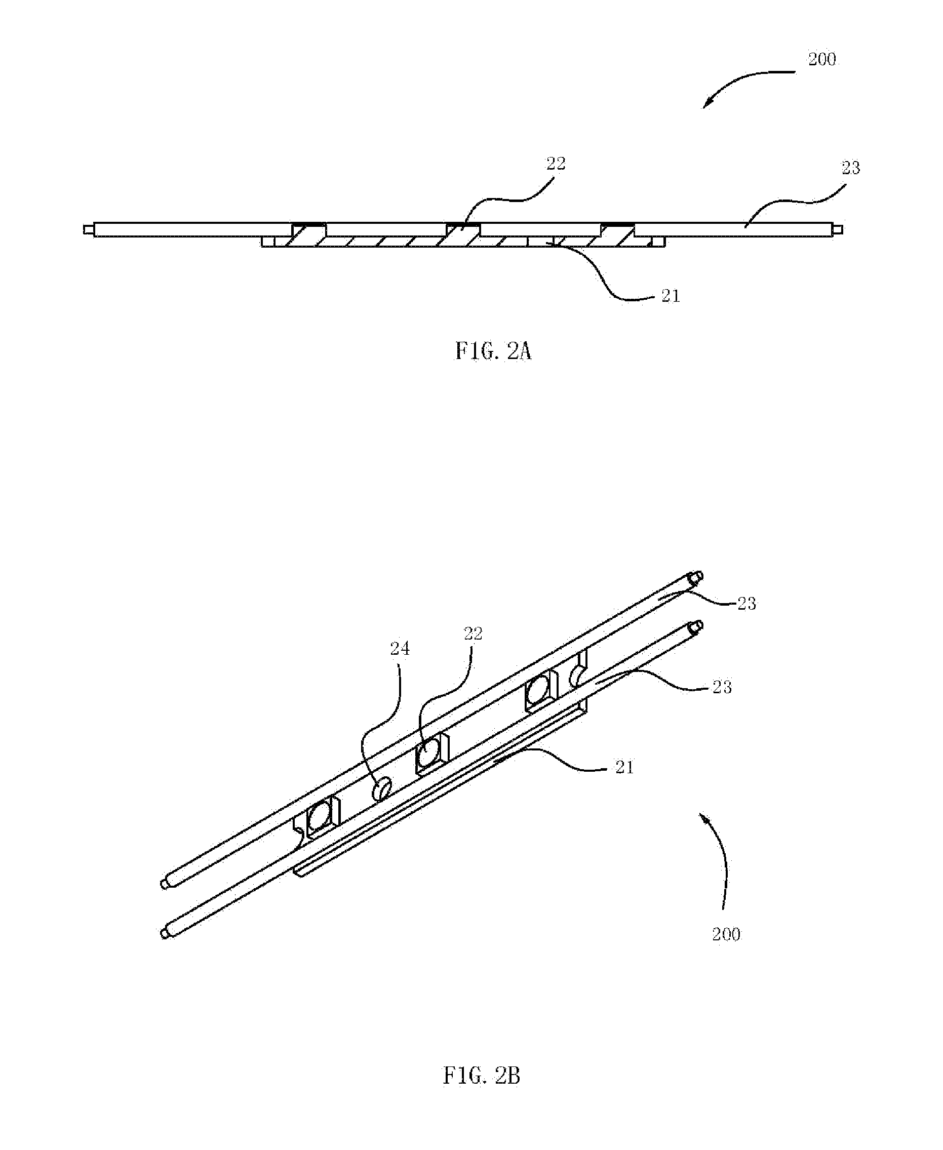
[0041]The non-waterproof model described herein may comprise a circuit board and at least one light emitting diode installed on the circuit board which is welded with an electronic component and a power line and covered by a plastic case, characterized in that, said circuit board is provided with at least two through holes. In certain embodiments, the bottom of the plastic case may be provided with at least two pins shaped and positioned to correspond for
mating with the through holes of the circuit board; said plastic case and said circuit board may be connected by inserting the pins into the through holes. It is noted that the number of pins is not critical and more or less may be desired for particular applications. In an embodiment, part of the pins which are inserted into through holes may be extended from the lower surface of the circuit board, and the cross sectional area of the extended pin part may be larger than that of through hole, forming a fixed pressure-fit (“
interference fit”) connection between the plastic case and the circuit board. The plastic case may be covered on the upper surface of the circuit board. In some embodiments, the plastic case may encapsulate the upper surface and periphery of the circuit board to form a half-encapsulation structure. In certain embodiments, the circuit board may have a elongated strip shape and be provided with a power line
welding part on the upper surface, and the power input line and
power output line are welded on two longer sides of the upper surface of the circuit board respectively. The through hole of said circuit board may be in the shape of cylinder, square or
diamond, or any shape applicable for a certain purpose. The circuit board may be provided with at least a first fixing hole, and a second fixing hole may be formed on said plastic case above the first fixing hole of the circuit board correspondingly, wherein the second fixing hole may be connected with the first fixing hole to form a through hole; the first fixing hole has any shape, including the shape of cylinder, square or
diamond. Said second fixing hole may be inserted into the first fixing hole and part of it may be extended from the lower surface of the circuit board. The circuit board described in this disclosure may be a metal substrate or PCB. In certain embodiments, the plastic case may form a light extraction hole on the light extraction surface of the light emitting diode; said light extraction hole may have the shape of inverted-trapezoid, cylinder or square, for example. The light emitting diode described in this disclosure may be a white LED or three
primary color full-color LED. Said light emitting diode may be a surface mountable light emitting diode.

