Carbon dioxide removal systems

a carbon dioxide and system technology, applied in the field of carbon dioxide removal systems, can solve the problems of significant amount of effort, no satisfactory results, and doubt that the world will give up or even materially reduce the use of fossil fuels (i.e., coal, petroleum natural gas) in the foreseeable futur

Inactive Publication Date: 2012-01-05
COAWAY
View PDF8 Cites 16 Cited by
  • Summary
  • Abstract
  • Description
  • Claims
  • Application Information

AI Technical Summary

Problems solved by technology

However, while some or all of these initiatives may play a significant role in our energy future, it is doubtful that the world will give up or even materially reduce its use of fossil fuels (i.e., coal, petroleum natural gas) in the foreseeable future.
Thus a significant amount of effort has been directed towards the development of processes which could capture, sequester and/or reuse carbon that would otherwise be vented into the atmosphere.
Many potential solutions have been considered but none are entirely satisfactory.
However, it appears that this will be very expensive, and whether buried CO2 will remain permanently underground is unknown.
Unfortunately, nuclear power would require a huge capital investment and for this reason as well as its associated “fear factor” would make a massive switch to nuclear power very highly unlikely.
On the other hand, renewable energy sources (i.e., wind, solar, hydro, etc), have cost, capacity limitations, and other impediments that will make it very hard for these niche players to significantly impact the dominance of fossil-based electrical generation.
However, removing CO2, which is a very dilute gas in the atmosphere, is a technically demanding problem.
Unfortunately, this approach is prohibitively expensive.
To capture and

Method used


Image

  • Carbon dioxide removal systems
  • Carbon dioxide removal systems
  • Carbon dioxide removal systems

Examples


example 1

Plant Configurations Using Waste Heat from Oil Refinery Flare Gas &“Pseudo Cooling Towers” to Capture Coτusing an Absorber / Spray Column

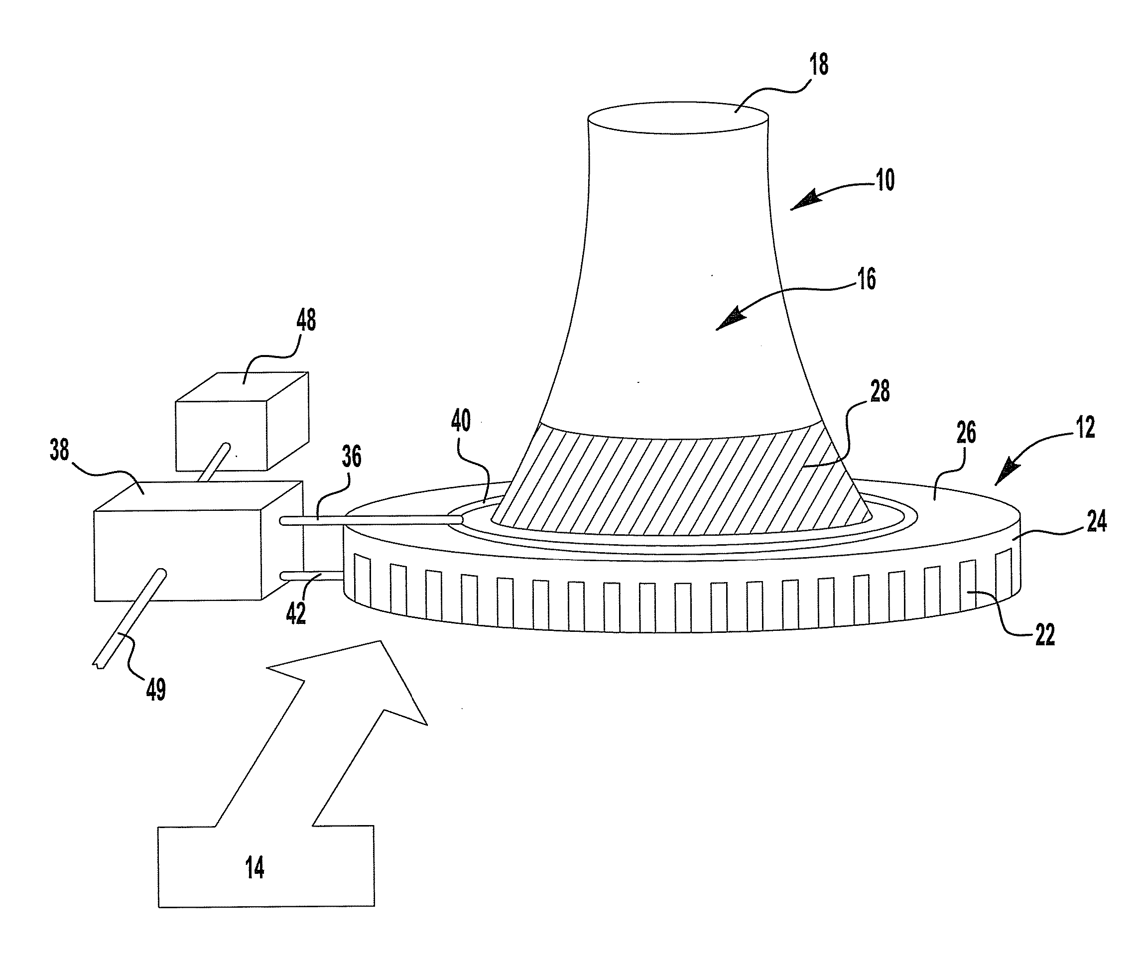
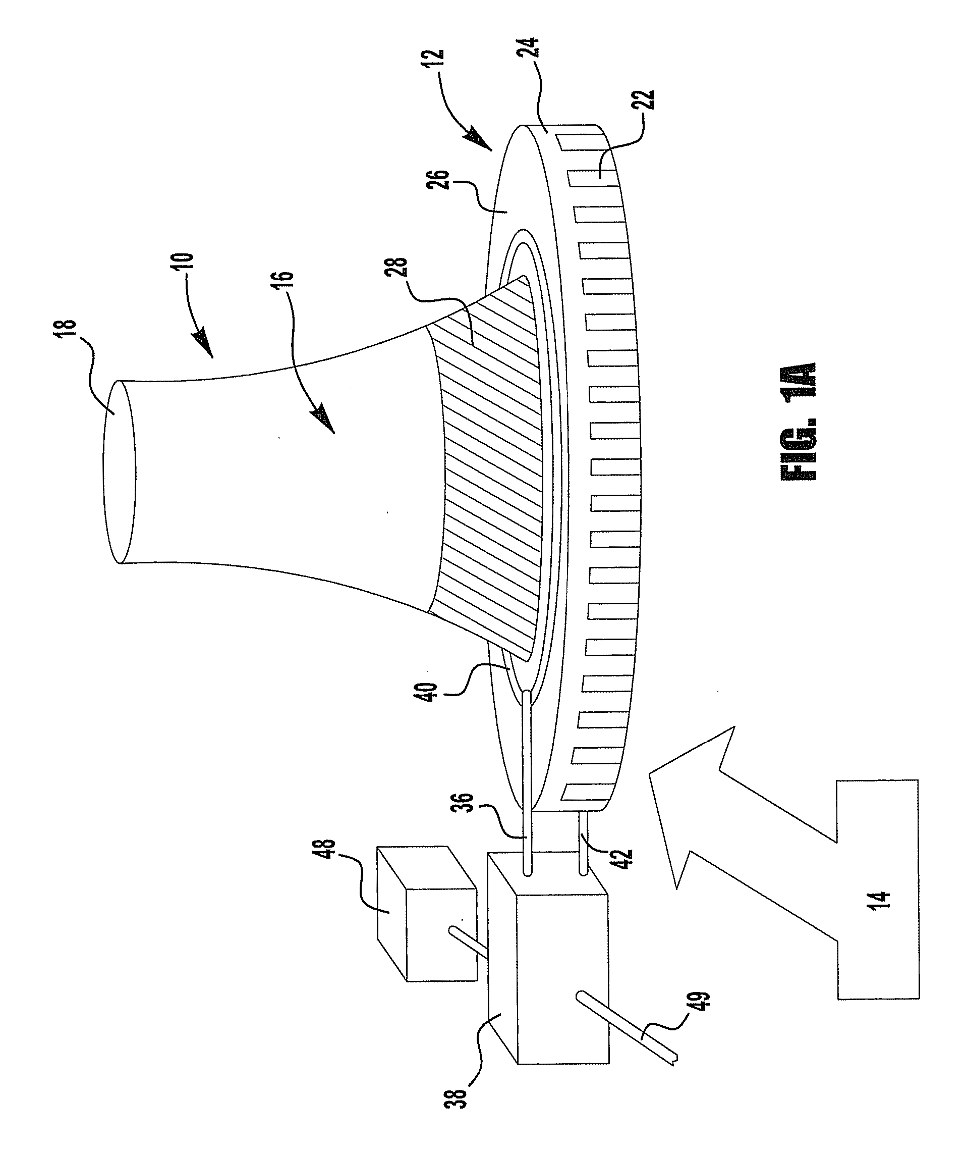
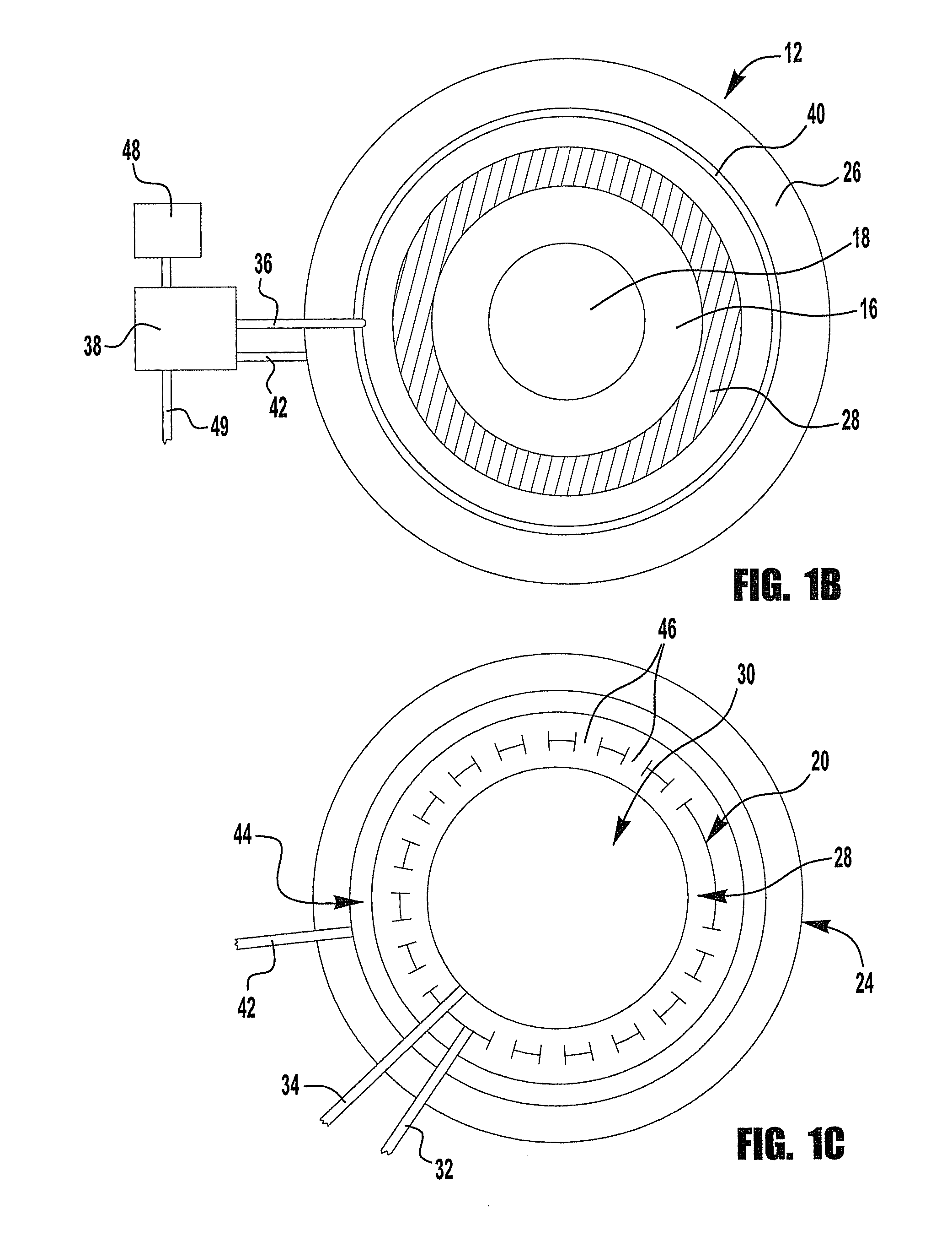
[0098]This example describes the use of waste flue gas from an industrial power source (e.g., a refinery) to heat air in a pseudo cooling tower constructed to simulate the flow of atmospheric air in a power plant cooling tower. A schematic representation of this embodiment of the invention is shown in FIG. 4. The flare gas is burned with a separate source of air by burners that are inserted in the middle section of the pseudo-cooling tower. The combustion gases mix and heat the air towards the top section of the pseudo-cooling tower 50 thus reducing the density of the gases at the top pseudo-cooling tower and causing the air to flow up, drawing atmospheric air 14 into the pseudo-cooling tower 50. At the same time a concentrated K2CO3 solution is sprayed down from the top the pseudo-cooling tower, allowing it to absorb the CO2 from the rising air and ...

example 2

Plant Configurations Using Waste Heat from Oil Refinery Flare Gas &“Simulated Cooling Towers” to CO2 Using a Wetted Wall CO2 Absorber

[0111]In many respects the second example is similar to that provided in Example 1. A schematic representation of this embodiment of the invention is shown in FIG. 5. Here again waste flue gas from an industrial power source (e.g., a refinery) is used to heat air in a pseudo-cooling tower 50 constructed to simulate the flow of atmospheric air in a power plant cooling tower. The flare gas burners, pointing upward are inserted midway in the pseudo-cooling tower 50 in order to heat the air and combustion gases in the upper section of the pseudo-cooling tower. Therefore the density of the air and combustion gases above this point is lower than that at the bottom of the pseudo-cooling tower causing air flow not unlike that in a power plant natural draft cooling tower with air migrating up in the pseudo-cooling tower.

[0112]Assuming a 20° F. (11.1° C.) increa...

example 3

Flare Gas Required to Move Air from Atmosphere Through Pseudo-Cooling Tower

[0122]The amount of air that can be heated by flare gas produced by a 150,000 bbl / day oil refinery is based on the following numbers and calculations. The conditions are those described in Example 1. The CO2 output from flare gas combustion produced by average refinery is about 0.0425 T CO2 / bbl, based on US Refineries CO2=304.8×10⁶ T CO2 / yr & Capacity=17.7×10⁶ bbls oil / day). The BTU value of flare gas=1583 BTU / ft3 & CO2=0.203 lbs / ft3 of flare gas, based on composition & heat of combustion Hydrocarbon Processing tables. Lb CO2ZMMBTU=0.203×10⁶ / 1583=128 lb / MMBTU.

[0123]The amount Of CO2 from flare gas at 150,000 bbl / D=150×103×0.0425=6,375 T CO2 / D. The heat generated by flare gas=6375×2000 / 128 lb / MMBTU=0.1×10¹² BTU / D. The amount of atmospheric air that can be heated to raise temp by 20° F. is calculated by tons Air / D=0.1×10¹² BTU / D / (29 lb / mol×7 BTU / mol-F 20° F.×2000)=10.4×10⁶ T / D. The CO2 capture from atmospheric ...


PUM

PropertyMeasurementUnit
Temperatureaaaaaaaaaa
Fractionaaaaaaaaaa

Abstract

A system for removing CO2 from air such as atmospheric air is described that uses a cooling tower, a pseudo-cooling tower, or a wind capture device to provide a large volume of atmospheric air. A CO2 capture apparatus is positioned to contact atmospheric air moving towards or within the cooling tower, pseudo-tower, or wind capture device, and includes wherein the CO2 capture apparatus includes a CO2 binding agent that binds to CO2 in atmospheric air. An associated reprocessing apparatus releases C02 from the binding agent, directs the released CO2 to a CO2 storage chamber, and returns the binding agent to the CO2 capture apparatus. A system for removing CO2 from flue gas is also described.

Description

[0001]This application claims the benefit of PCT / US2010 / 027761, filed Mar. 18, 2010, U.S. Provisional Application Ser. No. 61 / 161,122, filed Mar. 18, 2009, U.S. Provisional Application Ser. No. 61 / 262,951, filed Nov. 20, 2009, and U.S. Provisional Application Ser. No. 61 / 289,498, filed Dec. 23, 2009, all of which are incorporated by reference herein.BACKGROUND[0002]It is now well known that during the last 150 years carbon-dioxide (CO2) concentration in the earth's atmosphere has increased by nearly 35% from approximately 280 to 385 parts per million (ppm), which today amounts to a total of about 3000 gigatonnes. Moreover, global annual emission of CO2 currently amounts to about 26 gigatonnes per year, of which 13 gigatonnes winds-up in the atmosphere (the rest being absorbed by the oceans) which is estimated to increase atmospheric CO2 by about 2 ppm / yr.[0003]Because of the rising level of these so called Green House Gasses (“GHG”) a great deal of discussion, concern and developmen...

Claims


Application Information

Patent Timeline
IPC IPC(8): C12N1/12E21B43/00A62B7/08C12M1/00B01D53/14A23L2/54
CPCB01D53/1475B01D53/185B01D53/62B01D53/78B01D2251/304Y02C10/08B01D2251/606B01D2257/504Y02C10/04Y02C10/06B01D2251/306Y02A50/20Y02C20/40
Inventor POLAK, ROBERT B.STEINBERG, MEYER
Owner COAWAY
Why Eureka
Try Eureka