Rotary data and power transfer system

a power transfer system and data technology, applied in the direction of transformers/inductances, transformers, electrical equipment, etc., can solve the problems of difficult wet mating connection, difficult requirement, resistance contact point and failure of connector function, etc., to increase the distance over which information can be transmitted, improve data compression, and increase the useful information rate

Inactive Publication Date: 2012-01-12
WFS TECH
View PDF7 Cites 604 Cited by
  • Summary
  • Abstract
  • Description
  • Claims
  • Application Information

AI Technical Summary

Benefits of technology

[0050]Accordingly, an object of the present invention is to provide an improved underwater communication systems, and its methods of use, that uses electromagnetic waves for communication and propagation.
[0051]Another object of the present invention an underwater communication system, and its methods of use, for communication and propagation that increases the distance over which information can be transmitted.
[0052]Another object of the present invention an underwater communication systems, and its methods of use, for communication and propagation that increases the useful information rate.
[0053]Another object of the present invention an underwater communication systems, and its methods of use, for communication and propagation with improved data compression by reducing the transmitted bit rate.

Problems solved by technology

Electrical connections are a challenging aspect of underwater electrical system design, electrical conductive contact being the most common method of implementing an electrical mateable connector.
Electrically conductive contact connectors are commonly subject to corrosion and contamination, which can result in a resistive contact point and failure of the connector function.
Wet mating connections are even more challenging since water must be expelled from the conductive contacts during mating and care must be taken to ensure the signal is not applied to the connector while the contacts are exposed to the water before the connection is made to avoid rapid electrolytic corrosion.
This requirement can be problematic, particularly in applications where the connection point is not readily accessible by an operator such as connection by an autonomous system deep in the ocean.
Slip ring connectors have been designed to avoid this issue but typically employ conductive brush contacts which are subject to corrosion and contamination issues, suffer continuous mechanical wear in rotating applications and present the challenging requirement of an underwater sealed rotating mechanical joint to exclude water from the brush contacts.
A problem with such systems is that they are degraded by noise and interference from a number of sources.
They are also subject to multi-path effects and in some environments are virtually unusable.
Whilst the communications systems of WO01 / 95529 and GB2163029 have some technical advantages over more conventional acoustic or radio link systems, the functionality described is limited, and for many practical applications the available bandwidth is highly restrictive, as is distance over which data can be transmitted.
However, for propagating electromagnetic waves the energy is continually cycling between magnetic and electric field and this results in attenuation of propagating waves due to conduction losses.
The attenuation losses, the bandwidth restrictions and the limited distances over which data can be transmitted all pose significant practical problems for underwater communications.
Existing methods of acoustic communication are inherently restricted in the distance they can achieve at effective data rates.
The existing art of electromagnetic communication under water fails to recognize measures that can be taken to maximize the distance and / or useful information rate which can be achieved by adapting the devices sourcing and using the information so that more effective signal frequencies can be adopted.

Method used


Image

  • Rotary data and power transfer system
  • Rotary data and power transfer system
  • Rotary data and power transfer system

Examples


Embodiment Construction

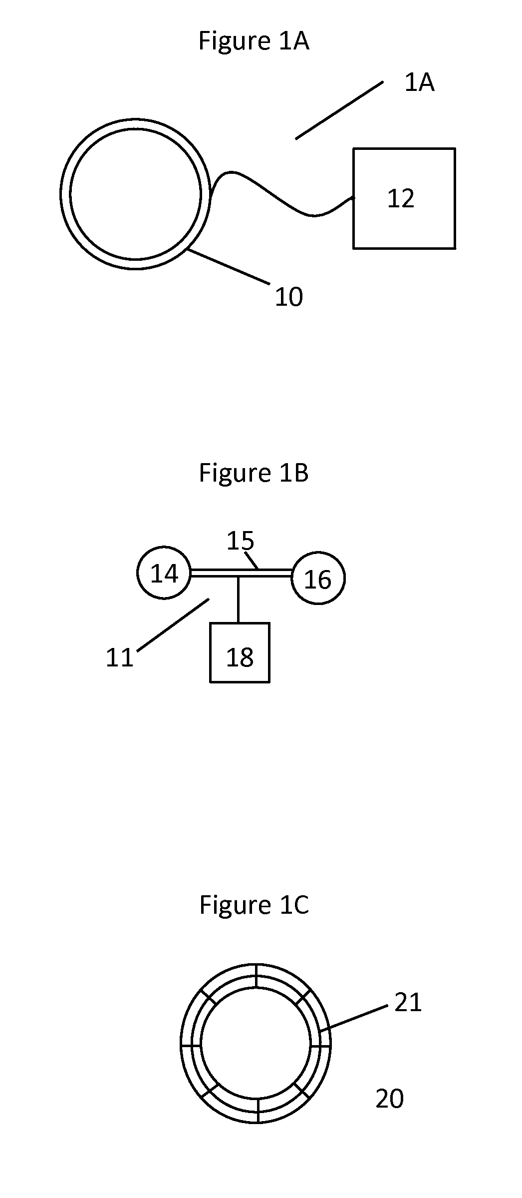
[0082]In FIG. 1A there is shown an example embodiment of a through water communications element 1A which is in this case has a radio transmission component which in this case is a loop antenna 10 which combines transmit and receive loop antenna windings in a single overall outer jacket. As can be seen, antenna 10 interfaces to radio modem unit 12. In FIG. 1B there is shown an alternative example embodiment of the through water radio communications element 1B which comprises electrodes 14 and 16 connected by cable 3 to form an electric dipole antenna 11 which interfaces with radio modem 18. In FIG. 1C there is shown a rotary transformer element 20 which, in use, interfaces with a similar transformer (not shown) to couple electrical power without conductive contact.

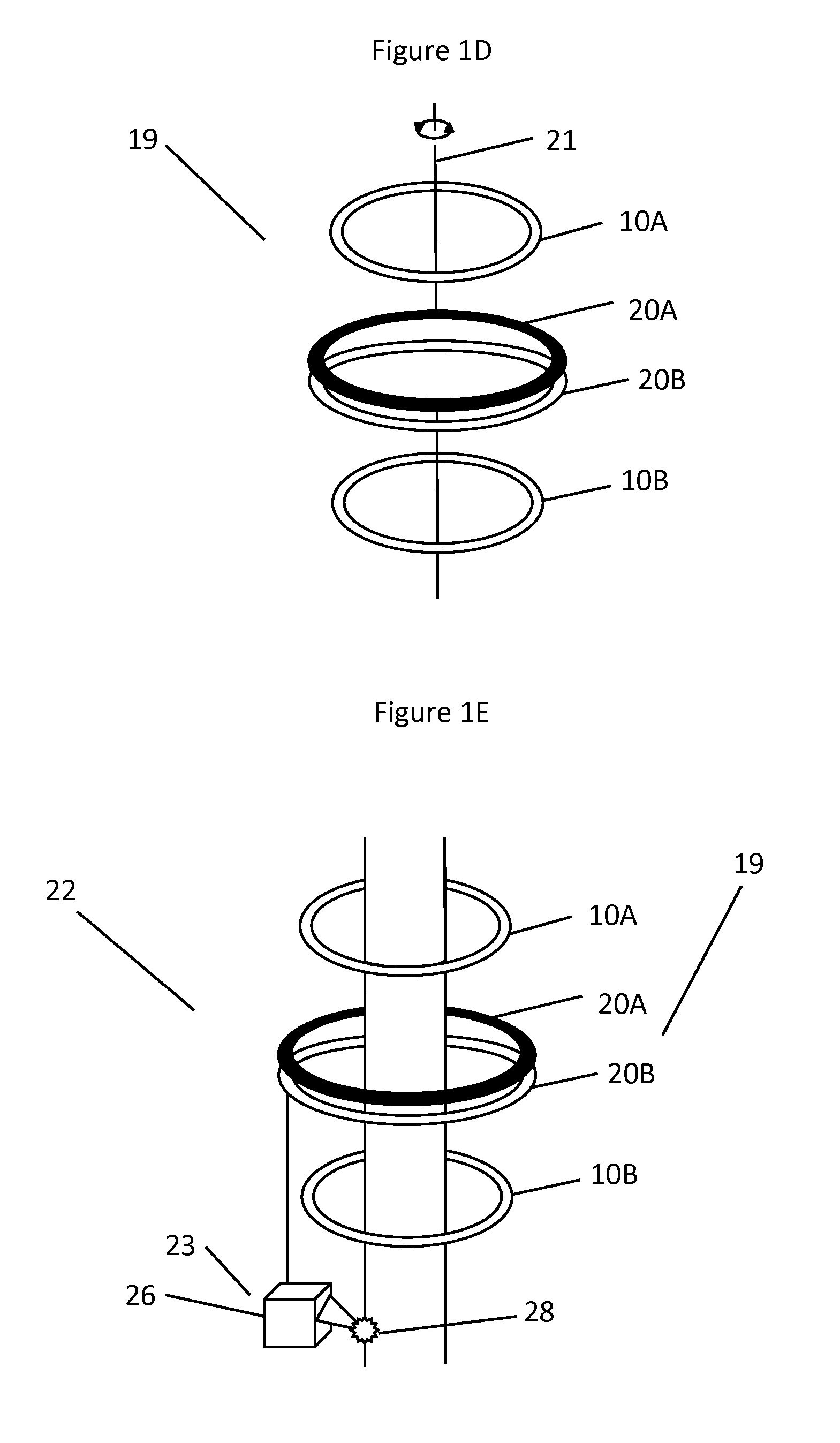
[0083]FIG. 1D illustrates a relative positioning of components arranged for use as one embodiment of an off axis rotary and power transfer system of the present invention. As can be seen, radio modem transducer loop 10A is ...


PUM


Abstract

A data and power transfer system comprising a first system unit which includes a first communication element operable to transfer communication signals and a first connector element operable to transfer electrical power; and a second system unit which includes a second communication element operable to transfer communication signals and a second connector element operable to transfer electrical power, wherein the first communication element and second communication element are operable to transfer data between one another and the first connector element and second connector element are operable to transfer electrical power whilst electrically insulated from one another.

Description

CROSS-REFERENCE TO RELATED APPLICATIONS[0001]This application is a continuation-in-part of U.S. Ser. No. 12 / 366,856, which application is fully incorporated herein by reference.FIELD OF THE INVENTION[0002]The present invention relates to a connector system providing transfer of electrical power and data communications signals between two systems. The connector has no conductive electrical connection and can operate independently of angular orientation.BACKGROUND OF THE INVENTION[0003]Electrical connections are a challenging aspect of underwater electrical system design, electrical conductive contact being the most common method of implementing an electrical mateable connector. Electrically conductive contact connectors are commonly subject to corrosion and contamination, which can result in a resistive contact point and failure of the connector function. In under water applications water must be excluded from the conductive contacts to prevent short circuits due to the partially con...

Claims


Application Information

Patent Timeline
Patent Type & Authority Applications(United States)
IPC IPC(8): H02J17/00
CPCH01F38/14H01F2038/143H01F38/18
Inventor RHODES, MARKHYLAND, BRENDAN
Owner WFS TECH
Why Eureka
Try Eureka