

High frequency measurement system
a measurement system and high frequency technology, applied in the direction of frequency analysis, transmission, selection arrangement, etc., can solve the problems of unsatisfactory use of traditional multiplexer devices and demultiplexer devices in the measurement method of high-frequency behaviour of duts, non-linear behaviour of such devices, and unsatisfactory use of traditional multiplexer devices and demultiplexer devices. , to achieve the effect of improving one or more of the efficiency, gain, or maximum power output of the circui
- Summary
- Abstract
- Description
- Claims
- Application Information
AI Technical Summary
Benefits of technology
Problems solved by technology
Method used
Image

Examples
first embodiment
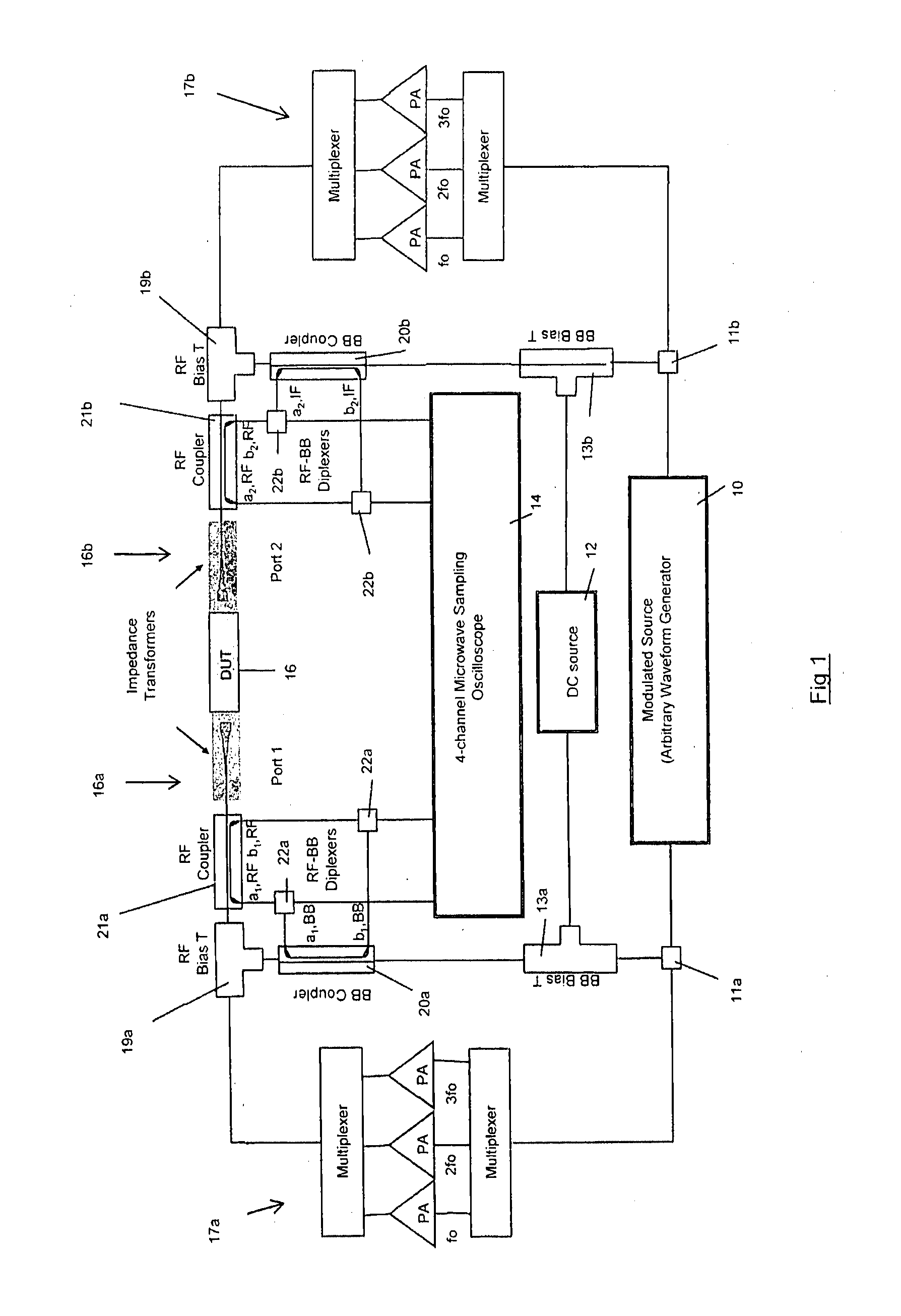
[0062]FIG. 1 is a schematic circuit diagram showing a high frequency non-linear measurement system according to the present invention. The measurement system is based around a VNA (vector network analyser with integrated source). The VNA thus comprises a modulated source (arbitrary waveform generator) 10, DC source 12 and a microwave sampling oscilloscope 14. It will be appreciated that those three components can be provided in one product by means of commercially available vector network analysers.
[0063]The measurement system is arranged to measure characteristics bf a two-port device under test (DUT) 16. The modulated source generates not only the base-band modulation signal, having a frequency in the MHz range, but also the RF signals in the GHz range. The base-band signal is divided out from the signals outputted by the modulated source 10, by means of two diplexers 11, one 11a arranged to feed the input side of circuit and one 11b arranged to feed the output side of circuit. Th...
second embodiment
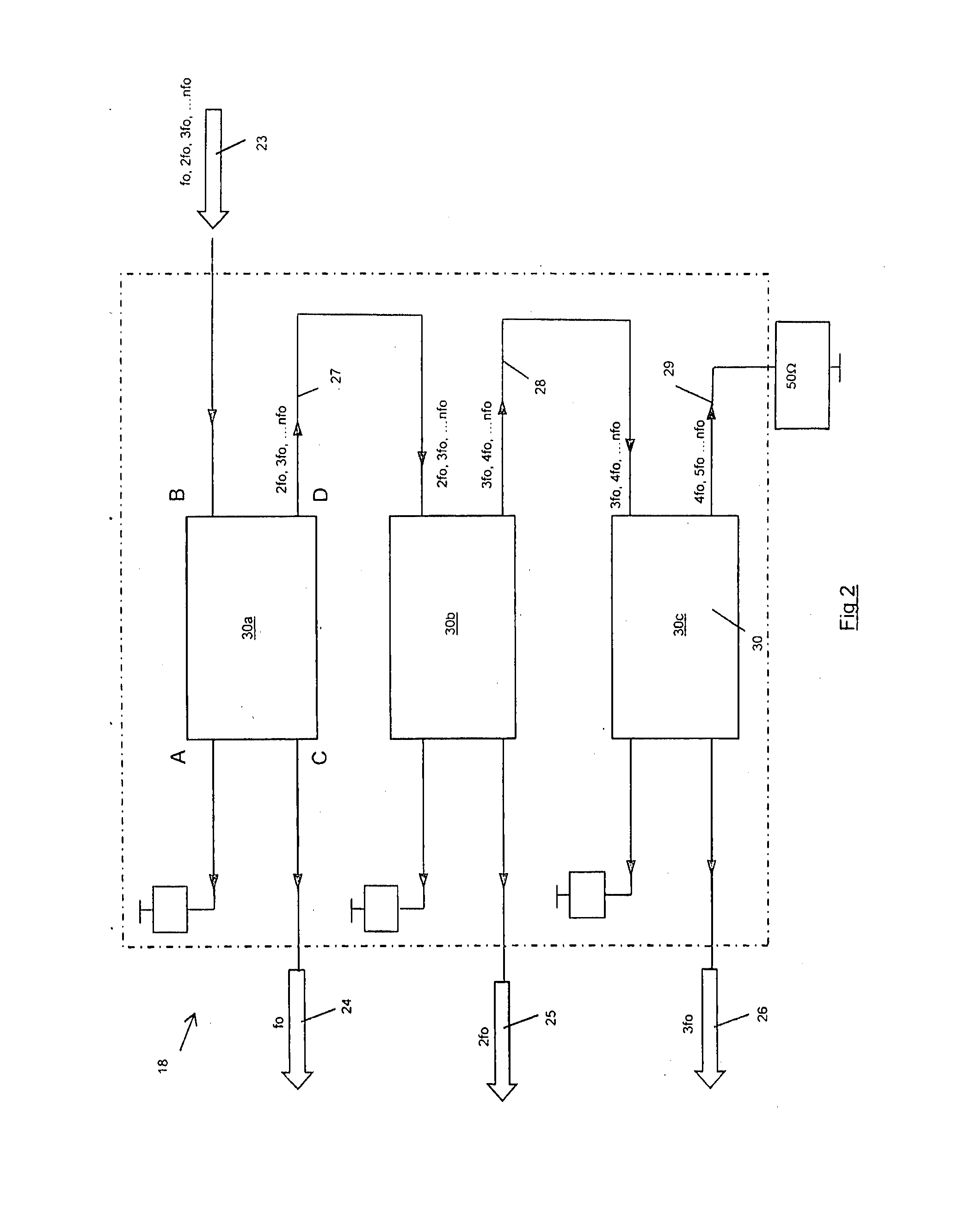
[0076]FIG. 5 shows a multiplexer circuit 118 according to the invention. It will be seen that the structure of the circuit 118 is very similar to that shown in FIG. 4. However, in this case, the multiplexer is used in a high frequency non-linear measurement system to combine four RF signals into a single combined signal, and as such the signal splitting circuits operate in reverse to combine signals. Thus, there are three signal splitting circuits 130a, 130b, 130c arranged in a cascade. To avoid confusion the circuits 130a, 130b, 130c in FIG. 5 will now be referred to as “signal combining circuits”. The principles of operation of each signal combining circuit is substantially identical to the principles of operation of the signal splitting circuit shown in FIGS. 3a to 3c, except that the signal combining circuit is used in reverse. Thus, at the fourth port of the third signal combining circuit 130c an input signal 129 at the third harmonic frequency 4f0 is received. An input signal ...
third embodiment
[0077]It will be appreciated that multiplexer circuits for combining or splitting RF signals with very little power loss and with very little reflection can be made from a variety of different arrangements and configurations of hybrid couplers and RF filters. For example, high pass, or band-pass filters could be utilized. FIG. 6 shows as an example a multiplexer circuit (arranged for demultiplexing a composite signal) according to the invention, which utilizes high-pass filters. The principle of operation is very similar to that of the other illustrated multiplexer circuits. Thus, FIG. 4 shows how three such signal splitting circuits are combined to provide the function of the multiplexer circuit 18 illustrated in FIG. 2. Thus, a high-frequency multi-component signal 323 is received at a second port of a hybrid coupler 332 of a first signal splitting circuit (comprising couplers 332, 333 and high-pass filters 334, 336). The high-pass filters 334, 336 allow passage of signals with fr...
PUM
| Property | Measurement | Unit |
|---|---|---|
| Angle | aaaaa | aaaaa |
| Sound / signal amplitude | aaaaa | aaaaa |
| Frequency | aaaaa | aaaaa |
Abstract
Description
Claims
Application Information