
Carbon fiber electrical contacts formed of composite material including plural carbon fiber elements bonded together in low-resistance synthetic resin

a technology of carbon fiber and composite materials, applied in the direction of sliding contact resistor details, connection contact member materials, resistors, etc., can solve the problems of affecting the accuracy of output signals, price increases, and early termination of accurate performance and useful life, so as to improve the useful life of the system. , the effect of improving the useful li

Inactive Publication Date: 2012-01-12
MICRO CONTACTS
View PDF3 Cites 5 Cited by
  • Summary
  • Abstract
  • Description
  • Claims
  • Application Information

AI Technical Summary

Benefits of technology

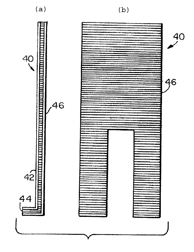
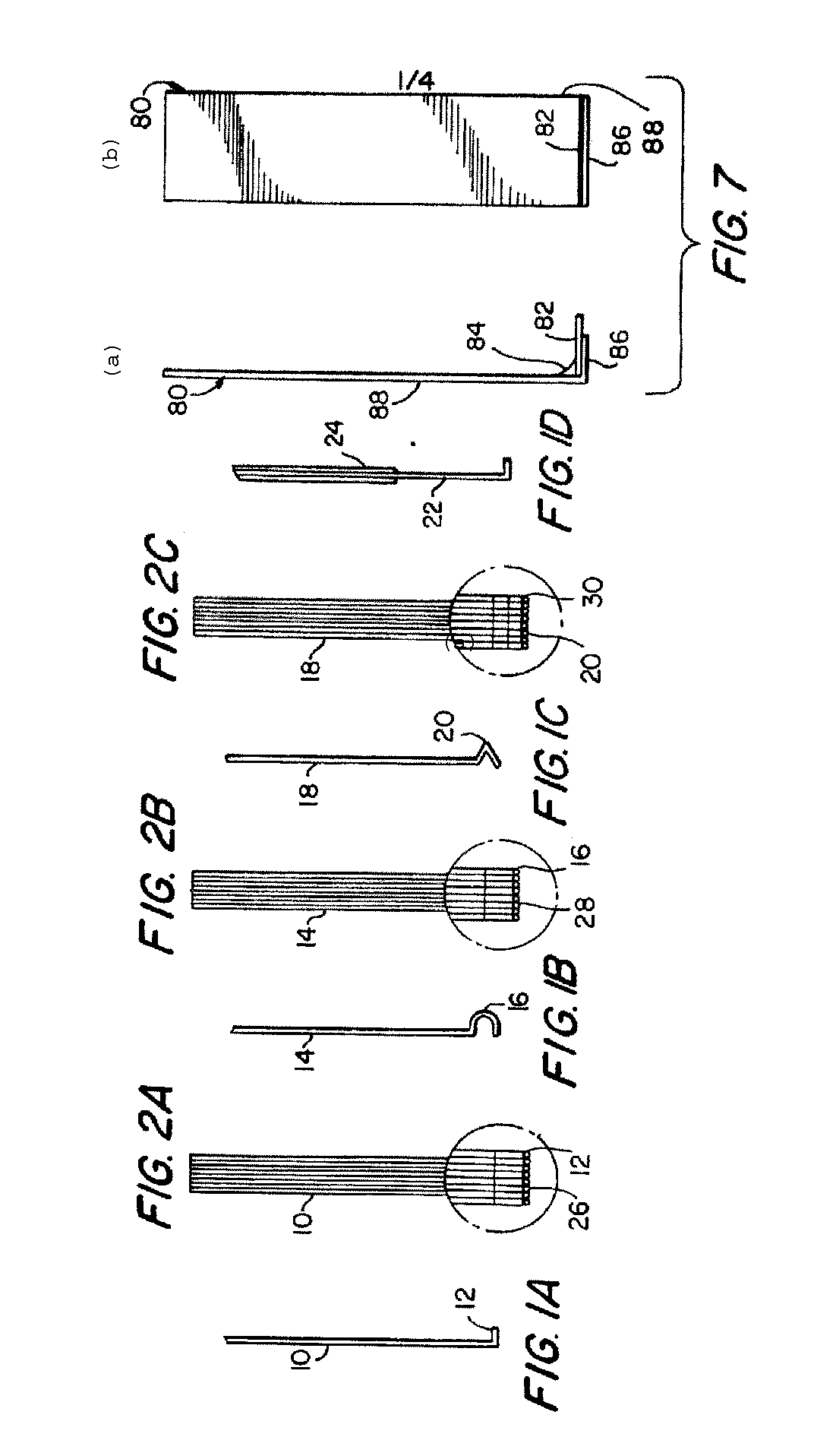
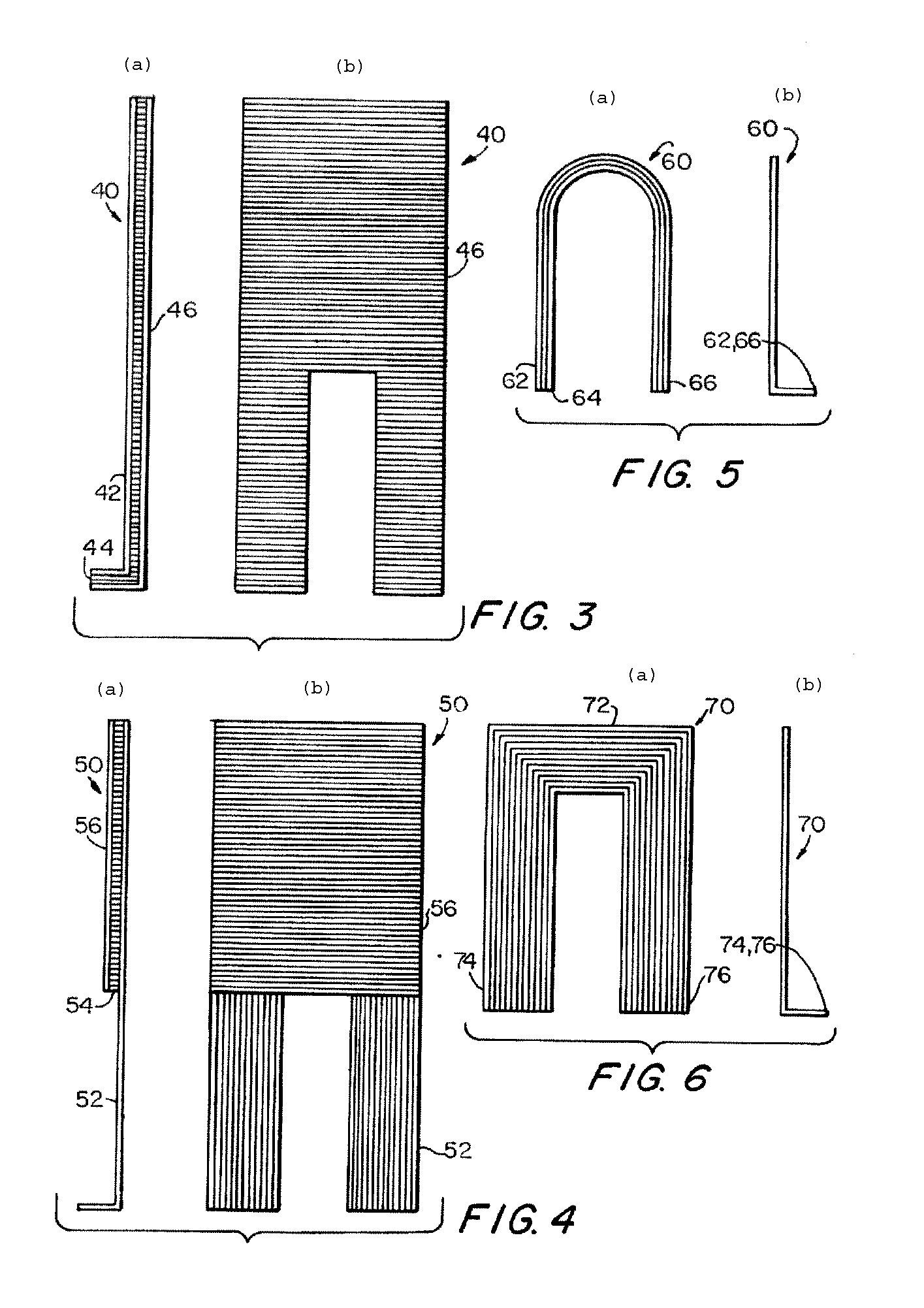
[0010]In an aspect of this disclosure, there is provided a contact or contact assembly for use in electromechanical applications that can improve considerably the useful life of the system by providing a contact or wiper formed of nonmetallic material, more specifically, one formed of a composite carbon fiber material including plural carbon fiber elements bonded together and firmly fixed in a semi-conductive (low-resistance) synthetic resin compound for structural stability and electrical continuity.

Problems solved by technology

Because these contacts or wipers are used in a dynamic state they cannot be fixed or restricted in their movement and must have the freedom to slide or move along any length of their respective resistive or conductive paths.
This results in the early termination of accurate performance and useful life.
As time evolved great improvements were made in the non-wirewound product area, and they supplanted the wirewound resistive element, but the contact or wiper has always created problems relative to the resistive element because in the presence of an electrical current and dynamic performance, the precious metal components of the metallic contact provide the catalyst to generate polymers and debris, which interfere with the accuracy of the output signal.
The price increase has been largely due to an uncertain supply of this metal.
The precious metal currently being used cannot be recycled, so that there will be a conflict with this mandate.

Method used


Image

  • Carbon fiber electrical contacts formed of composite material including plural carbon fiber elements bonded together in low-resistance synthetic resin
  • Carbon fiber electrical contacts formed of composite material including plural carbon fiber elements bonded together in low-resistance synthetic resin
  • Carbon fiber electrical contacts formed of composite material including plural carbon fiber elements bonded together in low-resistance synthetic resin

Examples


Embodiment Construction

[0026]This disclosure provides guidance to obtain a contact or wiper element for transmitting electrical signals, either in a low voltage mode (under 45 volts) or a low current mode (under 1000 ma), between a resistive and / or a conductive track and some external circuit termination.

[0027]In an aspect, there is provided a contact or wiper element comprises one or more thin, single layers of carbon fiber elements, all aligned in one direction bonded together and firmly fixed in a very low-resistance, synthetic resin compound for structural stability and electrical continuity and which form part of a composite carbon fiber material (various embodiments of which are described below). Such composite carbon fiber material, not only overcomes the negative conditions caused by metal composition contacts or wipers, but considerably improves total performance in many other aspects. The material is designed to facilitate a virtual drop-in replacement contact or wiper. Such wiper contact or con...


PUM

PropertyMeasurementUnit
Electrical conductivityaaaaaaaaaa
Structureaaaaaaaaaa
Shapeaaaaaaaaaa

Abstract

An electrical contact device, configured for electrical signals to be transmitted therethrough and for movable contact with an electrically conductive track, includes a composite carbon fiber material including plural carbon fiber elements aligned in substantially the same direction. At least a portion of the plural carbon fiber elements is bonded together in a semi-conductive (low-resistance) synthetic resin compound.

Description

CROSS-REFERENCE TO RELATED APPLICATIONS[0001]This application is a continuation-in-part of application Ser. No. 09 / 899,776 filed Jul. 5, 2001, which in turn is a continuation-in-part of application Ser. No. 09 / 498,872 filed Feb. 7, 2000 (now U.S. Pat. No. 6,444,102).TECHNICAL FIELD[0002]This disclosure relates generally to an electrical contact or an electrical contact assembly (such as used in an electromechanical device), and more particularly to a contact or contact assembly, which is formed of a composite material using plural carbon fiber elements bonded together and firmly fixed in a semi-conductive (low-resistance) synthetic resin compound, to collectively make electrical contact with another element of the electromechanical device.BACKGROUND[0003]Variable resistive devices utilize elements that vary a voltage or current in order to provide an electrical signal that indicates a relationship to a physical position of a contact or wiper on a resistive or conductive element. Bec...

Claims


Application Information

Patent Timeline
IPC IPC(8): H01C1/12
CPCH01C10/30H01R39/24H01C10/306
Inventor TUCCI, MICHAELURUBURU, PHILIPVESELASKI, STEPHEN
Owner MICRO CONTACTS
Learn More