Eureka AIR delivers breakthrough ideas for toughest innovation challenges, trusted by R&D personnel around the world.

Miniaturized electronic device ingestible by a subject or implantable inside a body of the subject

a miniaturized electronic device and body technology, applied in the field of body electronic devices, can solve problems such as limiting the detection range, and achieve the effects of improving the efficiency of transmitting antennas, increasing signal transmission data rates, and relatively low signal attenuation inside the body

Active Publication Date: 2012-01-12
UNIV OF FLORIDA RES FOUNDATION INC
View PDF10 Cites 35 Cited by
  • Summary
  • Abstract
  • Description
  • Claims
  • Application Information

AI Technical Summary

Benefits of technology

[0011]A single or multiple antennas may be used as radiating elements for communicating with external detectors. Moreover, antennas may be entirely embedded within the microchip to establish powering and communication protocols with the external reader. In addition, the tagging device may use one or two frequencies to power and communicate with the external reader. The choice of frequency can be optimized independently for powering and communications. For instance, one may choose to power the device at lower frequencies using galvanic signal coupling, as the signal attenuation inside the body may be relatively low; and the communication from the tag to the reader may be established using a higher frequency carrier using either near field or far-field coupling to improve the efficiency of the transmitting antenna and increase the signal transmission data rates.

Problems solved by technology

By way of comparison, passive (or battery-less) systems, such as RFID tags and transponders communicate by means of backscattering, generating at best only a fraction the power that is incident across the antenna ports, thereby limiting the detection range.

Method used


Image

  • Miniaturized electronic device ingestible by a subject or implantable inside a body of the subject
  • Miniaturized electronic device ingestible by a subject or implantable inside a body of the subject
  • Miniaturized electronic device ingestible by a subject or implantable inside a body of the subject

Examples


Embodiment Construction

[0037]In the following description of example embodiments, reference is made to accompanying drawings which are used to facilitate an understanding of aspects of the present invention.

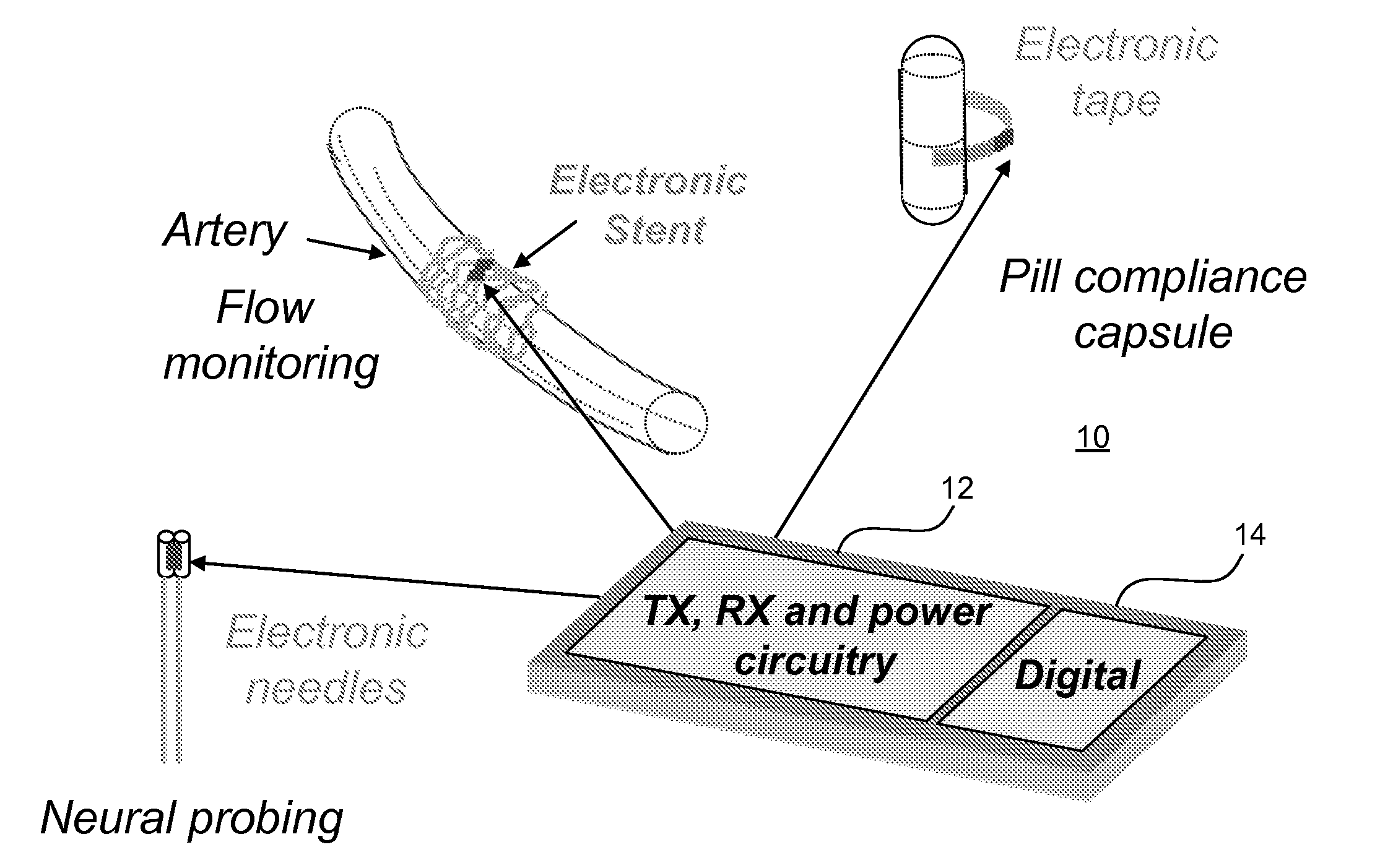
[0038]FIG. 1 is a schematic of an example passive micro-electronic system 10 that may benefit from aspects of the present invention. System 10, as may be manufactured using standard semiconductor processing such as complementary metal oxide semiconductor (CMOS) or any other suitable integrated circuit (IC) technology. The micro-electronic system may comprise a transceiver 12, a digital processor 14, and / or IC-compatible sensors, such as may be used for monitoring one or more parameters, such as pH level, temperature, oxygen levels, etc. The system, as may be constructed on an IC chip, is highly miniaturized so that it virtually invisible to the human eye, and may be inexpensively produced so that it can be fabricated in large numbers for high-volume applications (e.g., electronic pills, electronic sten...


PUM


Abstract

A miniaturized in-body electronic device is provided. One or more antennas (e.g., 32) may be galvanically coupled to receive an alternating current (AC) signal through the body of a subject where the in-body electronic device is located. Power extraction circuitry (e.g., 36) is configured to extract electrical power from the AC signal received by the antenna. The extracted electrical power is used for electrically powering one or more components of the electronic device. A transmitter (e.g., 48) is coupled to receive power from the power extraction circuitry. A controller (e.g., 46) is coupled to the transmitter. The controller is configured to activate the transmitter to generate a sequence of intermittent transmission bursts for transmitting an uplink signal. A transmission burst may have a higher instantaneous power level than an instantaneous power level of the AC signal received by the antenna.

Description

RELATED APPLICATIONS[0001]This application claims the benefit of U.S. Ser. No. 61 / 161,441 filed Mar. 19, 2009, under 35 USC§119(e) which is incorporated herein by reference in it entirety.FIELD OF INVENTION[0002]The present invention is generally related to in-body electronic devices, and, more particularly, to techniques and circuits for powering and communicating by way of miniaturized electronic devices inside humans or animals.BACKGROUND OF INVENTION[0003]Medication compliance is the degree to which a medication is taken according to a prescribed treatment and is usually measured in terms of percent of doses taken over a given interval. It is estimated that thousands of people may die of treatable ailments because of poor adherence and a tenth of hospital admissions are associated with noncompliance at a healthcare services expense of approximately $15.2 billion annually. Medication compliance is also important in the context of clinical drug trials, geriatrics, and mental healt...

Claims


Application Information

Patent Timeline
Patent Type & Authority Applications(United States)
IPC IPC(8): H04W88/02H04L27/00
CPCA61B2560/0219A61B5/0031A61B5/0028
Inventor RIZWAN, BASHIRULLAH
Owner UNIV OF FLORIDA RES FOUNDATION INC
Why Eureka
Eureka Blog
Learn More