
Method for Controlling and Recording the Security of an Enclosure

Inactive Publication Date: 2012-01-12
MICRO ENHANCED TECH
View PDF12 Cites 26 Cited by
  • Summary
  • Abstract
  • Description
  • Claims
  • Application Information

AI Technical Summary

Benefits of technology

[0018]It is a general object of the present invention to develop an electronic access control device which is easier to manufacture and more reliable to operate, and provides improved security to prevent tampering or unauthorized access.
[0019]It is an object of the present invention to provide an electronic access control device with a non-volatile memory for storing an access code that permits the manufacturer of the device to easily insert the access code into the device and then read out the code for verification.
[0020]It is an object of the present invention to provide an electronic access control device that provides significantly enhanced security and reduced vulnerability to tampering as compared to previous electronic locks.

Problems solved by technology

There are problems associated with previous electronic access control devices.
One area of problems concerns the manufacture of the devices, including the difficulty in programming the non-volatile memory, such as the EPROM, for storing the access code and other useful information for the operation of the device.
EPROMs, which usually require parallel programming, interrupt the manufacturing process in that they restrict when the manufacturer can program the device.
However, with parallel EPROMs, burning in the code after the device has manufactured is difficult.
After the device is soldered together, the manufacturer must contend with integrated circuit pin clips and must worry about interference with other circuitry on the manufactured device.
Further, manufacturing, with known electronic access control devices, requires many pin connections which increase manufacturing cost.
When the device contains a significant number of pin connections, the reliability of the device decreases.
However, with parallel EPROMs, serial access is not available.
One common problem associated with previous electronic locks is their potential vulnerability to tampering.
This arrangement is vulnerable to tampering because if the control circuit is somehow broken in or removed, one can open the lock by “hot-wiring” the control lines for activating the lock-opening mechanism.
Another technically challenging problem is related to the need to provide electrical energy to power the operation of the electronic access control device.
A battery, however, has a rather limited amount of electrical energy stored therein.
The operation of the low-battery detection circuit, however, also consumes electrical energy and contributes to the draining of the battery.
Although electronic keys are a convenient feature, they have their associated problems.
One problem is related to the unauthorized use of the keys.
There is a danger that such a master key may be used for unauthorized opening of other safes in the hotel.
Another problem associated with the use of an electronic key or a wireless access code transmitter is that the key or the transmitter may be lost easily, or the user may simply forget to bring the key or transmitter.
This problem is especially serious if the electronic access control device does not provide other means, such as a keypad, for entering the access code.
One significant problem with conventional vending machines is the difficulties in managing the distribution and usage of the keys to ensure the security of the locks on the vending machines.
The process of collecting money from the vending machines scattered at different places is a very manpower-intensive operation that requires many employees to go into the field with numerous mechanical keys for operating the locks on the vending machines.
It requires a considerable amount of attention and efforts to manage and track the distribution of the keys to the field workers to keep the keys secure.
Moreover, the mechanical keys and lock cores of vending machines are a point of attack for vandals.
The keys can be lost or copied easily, and the stolen or copied keys may then be used by an unauthorized person to access the machines, and it is difficult to discover such misuses and security breaches.
Also, a skilled vandal can easily pick or drill-out the lock core tumblers and measure the key cuts of the lock core tumblers to re-produce a like key and compromise the security.
In the event a security breach is identified, the mechanical lock cores of the affected vending machines typically have to be manually replaced, which is a time-consuming and very costly process.
Furthermore, mechanical keys and locks are devices that cannot be partially limited in operation they operate indefinitely if in use.
Also, they do not have the ability to record access operation attempts of their operation.

Method used


Image

  • Method for Controlling and Recording the Security of an Enclosure
  • Method for Controlling and Recording the Security of an Enclosure
  • Method for Controlling and Recording the Security of an Enclosure

Examples


Embodiment Construction

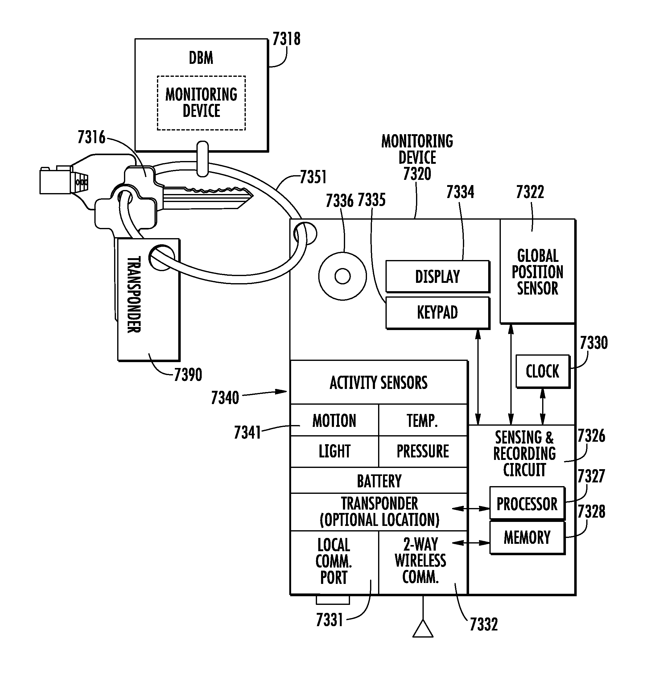
[0126]In an embodiment, an electronic system and method is provided for controlling access of devices. For instance, some devices operating in the field are in a relatively unsecured environment, and it is necessary to control the access or usage of the devices so that they are not accessed by unauthorized persons or that they are not used at unauthorized times or places. The devices that may be advantageously controlled using the system and method of the invention include, for example, safes, appliance devices such as vending machines, coolers, fountain drink dispensers, etc., power tools used in construction sites, shipping containers, and many other types of devices. It will be appreciated that the above list is meant only to provide some examples and is by no means intended to limit the applicability of the invention.

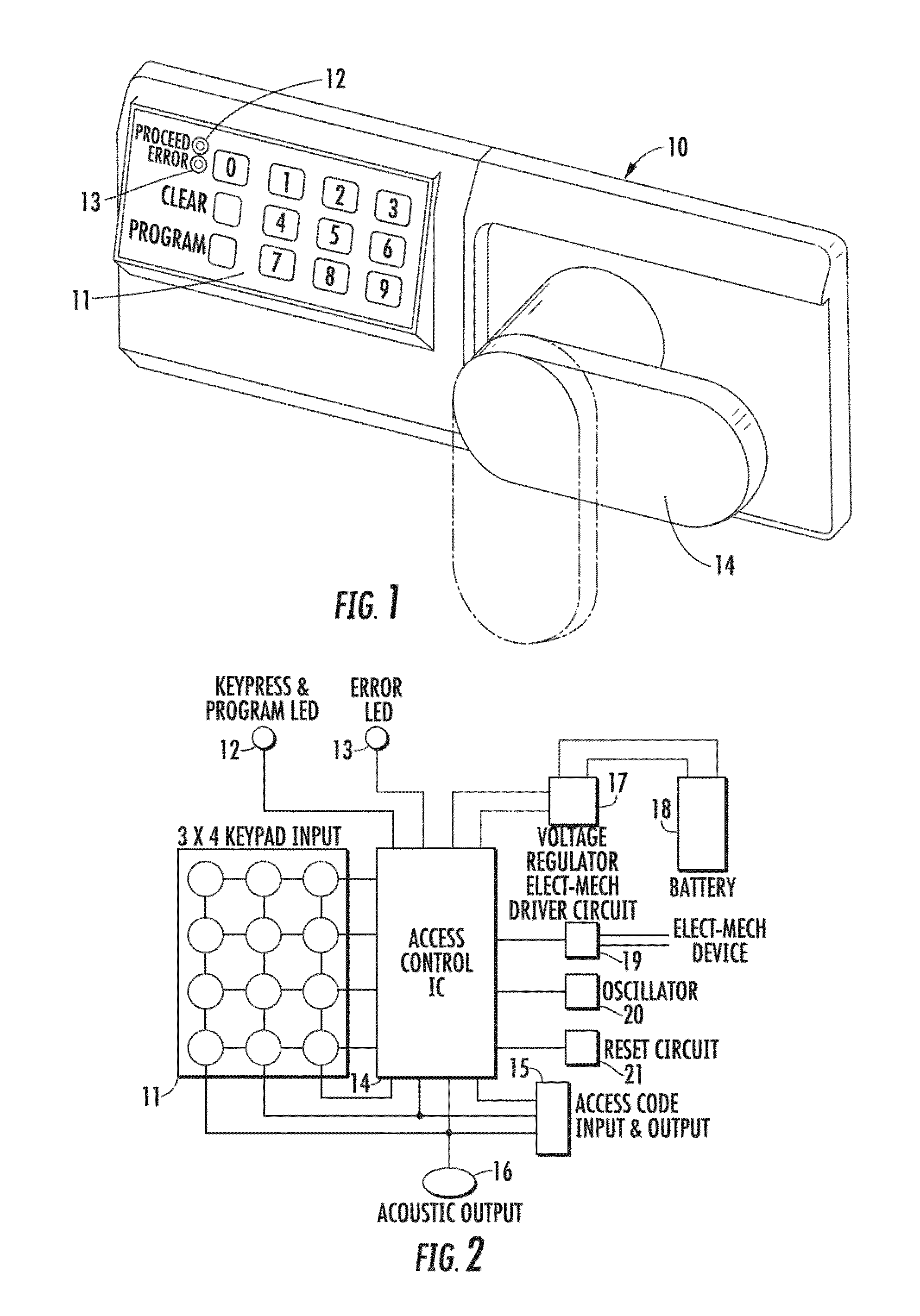
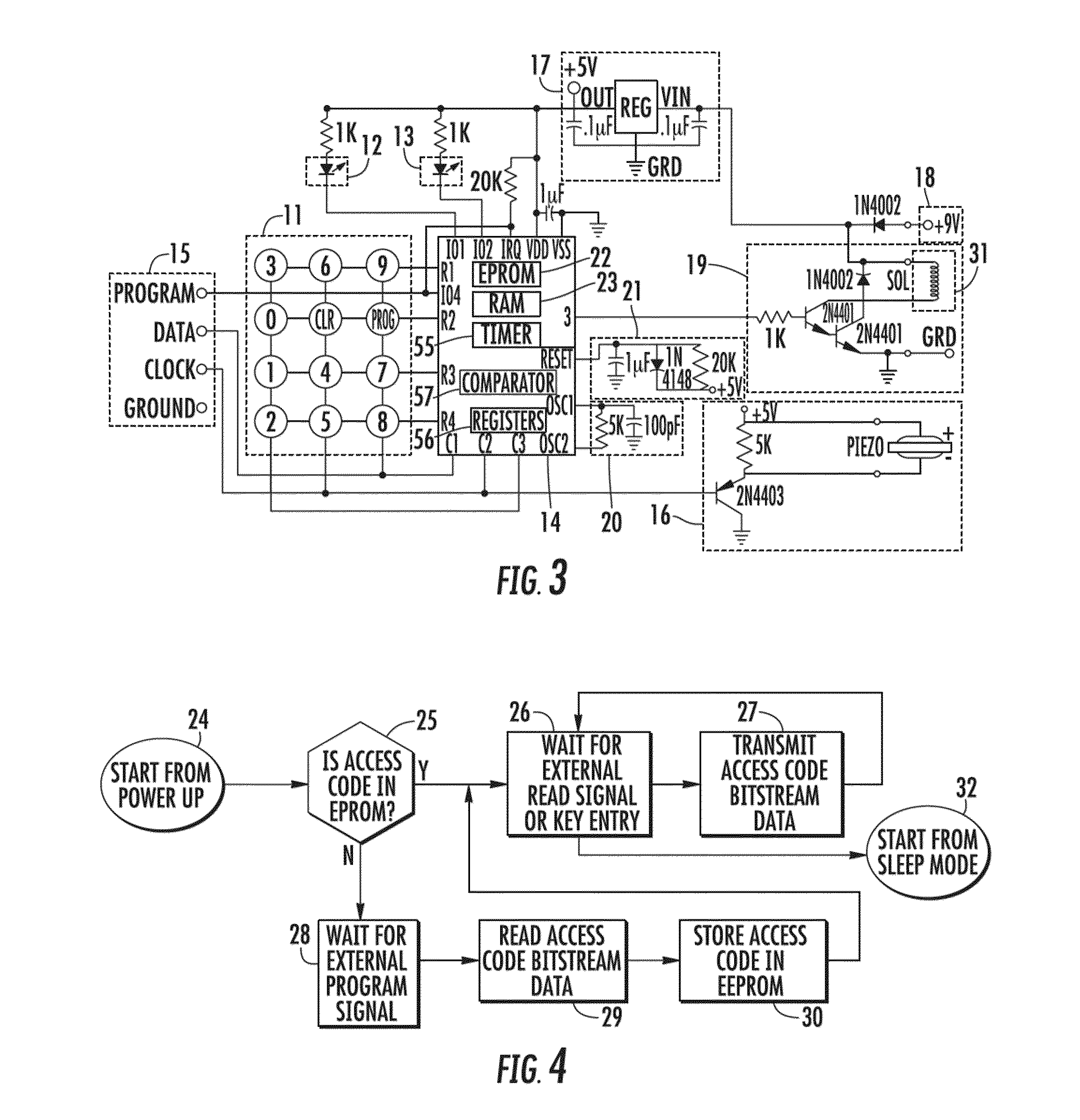
[0127]Referring to the drawings, there is shown in FIG. 1 an illustrative electronic access control device 10 having a keypad 11, light emitting diodes (LEDs) 12 an...


PUM


Abstract

A method for controlling and recording the security of an enclosure is disclosed. A mobile electronic control device, such as an electronic key, is used to access or otherwise control the operations of a field device, such as an appliance, power tool, shipping container, and the like. In a control event in which the mobile control device interacts with the field device via wired or wireless communications, the control device obtains the current location and the field device ID. The communications between the mobile control device and the field device may be secured with encryption. The location information is used by the mobile control device to determine whether the field device should be accessed or enabled. Alternatively, the location information may be stored separately in a location sensing device, and the control event data recorded by the key and the location information recorded by the location sensing device are later combined when they are downloaded into a management system for auditing. Moreover, an electronic access control device is disclosed comprising two microprocessors.

Description

CROSS-REFERENCE TO RELATED APPLICATIONS[0001]This application is a continuation-in-part of co-pending U.S. patent application Ser. No. 12 / 261,843, filed Oct. 30, 2008, which is a continuation of U.S. patent application Ser. No. 11 / 185,110, filed Jul. 20, 2005, and now abandoned, which was a continuation-in-part of (1) U.S. patent application Ser. No. 11 / 010,661, filed Dec. 13, 2004, and issued as U.S. Pat. No. 7,373,352, which claims the filing priority of U.S. Provisional Application Ser. No. 60 / 528,831, filed Dec. 11, 2003, and (2) U.S. patent application Ser. No. 10 / 838,449, filed May 4, 2004, which is a continuation-in-part of U.S. patent application Ser. No. 10 / 329,626, filed Dec. 26, 2002, and issued as U.S. Pat. No. 6,900,720, which claims the benefit of U.S. Provisional Application Ser. No. 60 / 344,221, filed Dec. 27, 2001. Each of the above-listed applications and patents is hereby incorporated herein by reference.[0002]This application is also a continuation-in-part of co-p...

Claims


Application Information

Patent Timeline
IPC IPC(8): H04L9/00G06F21/00G06F7/00
CPCE05B2047/0096G05B2219/24206G05B2219/25062G07F11/002G07C9/00571G07F5/26G07F9/026G05B2219/2613G07F9/002G07F9/001
Inventor DENISON, WILLIAM D.
Owner MICRO ENHANCED TECH
Learn More