Phosphor, method for producing same, light-emitting device, and image display apparatus

Inactive Publication Date: 2012-01-26
NAT INST FOR MATERIALS SCI
View PDF1 Cites 34 Cited by
  • Summary
  • Abstract
  • Description
  • Claims
  • Application Information

AI Technical Summary

Benefits of technology

[0011]A phosphor of the present invention comprises at least Li, Ca, Si, Al, O (oxygen), N (nitrogen), and Ce elements and exhibits high emission efficiency and high emission brightness as Ce is incorporated into the CaAlSiN3 crystal or a crystal having the same crystal structure as the CaAlSiN3 crystal (hereinafter, collectively being referred to as CaAlSiN3 group crystal) as a host crystal of the phosphor. Further, a phosphor having a specific composition in which an amount of Li and an am

Problems solved by technology

However, it is believed that none of the phos

Method used


Image

  • Phosphor, method for producing same, light-emitting device, and image display apparatus
  • Phosphor, method for producing same, light-emitting device, and image display apparatus
  • Phosphor, method for producing same, light-emitting device, and image display apparatus

Examples


example

[0100]The present invention will be described in more detail with reference to the examples to be shown below, but these examples are disclosed only for the purpose of facilitating understanding the present invention readily such that the present invention is not limited to these examples.

examples 1-32

[0101]As phosphors of the present invention, phosphors in Examples 1 to 14 were synthesized by controlling their compositions in order to emit yellow light; phosphors in Examples 15 to 28 were synthesized by controlling their compositions in order to emit orange light; and phosphors in Examples 29 to 31 were synthesized by controlling their compositions in order to emit red light.

[0102]In inorganic compounds: CeaLibAcAldSieXfOgNh (A is Ca by itself or a combination of Ca and Sr; X is metal element other than Ce, Li, Al, Si and A; and a+b+c+d+e+f+g+h=1 in the formula) including Ce, Li, Ca (and Sr), Al, Si, oxygen, and nitrogen, the compositions with the design parameters (atomic fractions): a, b, c, d, e, f, g, and h as shown in Table 1 were examined; and in inorganic compounds: Ce+x1LiSi2N3+x2CaAlSiN3+x3SrAlSiN3+x4Si2N2O (x1, x2, x3, and x4 are numerical values of at least zero (0) and not exceeding one (1) to indicate fractions; and x1+x2+x3+x4=1 in the formula), the compositions w...

example 32

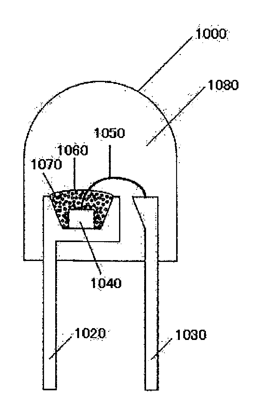
[0144]FIG. 10 is a schematic diagram showing the light-emitting device (bullet-type white light-emitting diode lamp) according to the present invention.

[0145]A so-called bullet-type white light-emitting diode lamp 1000 as shown in FIG. 10 was produced. A lead wire 1030 of two lead wires 1020 and 1030 has a recess and a blue light-emitting diode element 1040 is placed in the recess. The lower electrode of the blue light-emitting diode element 1040 and the bottom surface of the recess are electrically connected with conductive paste, and the upper electrode and the lead wire 1030 are electrically connected by a gold filament 1050. The phosphor of a yellow color emission produced for Example 2 was adopted for the phosphor 1070. The phosphor 1070 was dispersed in a first resin 1060 and mounted in the vicinity of the blue light-emitting diode element 1040. The first resin 1060 in which this phosphor 1070 was dispersed was transparent, and covered the entire blue light-emitting diode elem...


PUM


Abstract

A phosphor comprising a CaAlSiN3 group crystal as a host crystal and emitting highly-intense light, a manufacturing method and an application of the same are provided. In the present invention, the phosphor comprises at least lithium (Li), calcium (Ca), silicon (Si), aluminum (Al), oxygen (O), nitrogen (N), and cerium (Ce) elements, and has a CaAlSiN3 crystal or a crystal having the same crystal structure as CaAlSiN3. And a phosphor emitting yellow, orange, or red luminescence can be produced by controlling a composition thereof.

Description

FIELD OF THE INVENTION[0001]The present invention relates to a phosphor comprising a CaAlSiN3 group crystal as a host crystal and a manufacturing method and an application of the same.BACKGROUND ART[0002]A phosphor which emits green light, yellow light, orange light, red light or the like is utilized in a fluorescent display tube (VFD), a field emission display (EFD), a plasma display panel (PDP), a cathode-ray tube (CRT), a white color emission diode (LED), and so on. In any of these applications, it is necessary to provide the phosphor with energy to excite the phosphor in order to make the phosphor emit the fluorescence and the phosphor is excited by an excitation source with high energy such as a vacuum ultraviolet ray, an ultraviolet ray, an electron beam, blue light, or the like so as to emit a visible light ray.[0003]A phosphor having nitride as a host crystal is used for these applications (for example, refer to patent reference 1). The patent reference 1 reports a phosphor ...

Claims


Application Information

Patent Timeline
IPC IPC(8): H01J1/63C01B33/00C09K11/79
CPCC09K11/7715H01J2211/42H01J2329/20H01L33/502H01L2224/48247H01L2224/8592H01L2224/73265H01L2224/48091H01L2224/45144H01L2924/00014H01L2924/00H01L2924/181H01L2924/00012C09K11/64C09K11/08C09K11/59
Inventor HIROSAKI, NAOTO
Owner NAT INST FOR MATERIALS SCI
Why Eureka
Try Eureka