Axle Sleeve Manufacturing Process

Inactive Publication Date: 2012-02-09
THE NAT MASCH CO
View PDF6 Cites 20 Cited by
  • Summary
  • Abstract
  • Description
  • Claims
  • Application Information

AI Technical Summary

Benefits of technology

[0020]Another advantage of the present invention is the creation of improved mechanical properties within the finished component. The forging process improves the direction of the material grain and improves the mechanical properties of the sleeve as compared to manufacturing from bar stock.
[

Problems solved by technology

Given the weight sensitivity of these applications, these cylindrical sleeves typically have a difficult combination of thin wall and precision tolerances.
However, such is not currently economically viable, as will become apparent below.
However, the rough machining process 20 creates a large amount of wasted material 30 as the interior of the hollow formed shape is removed and not used for the final product.
Since the use of titanium allows has a relatively high cost premium, the creation of this large amount of

Method used


Image

  • Axle Sleeve Manufacturing Process
  • Axle Sleeve Manufacturing Process
  • Axle Sleeve Manufacturing Process

Examples


Example

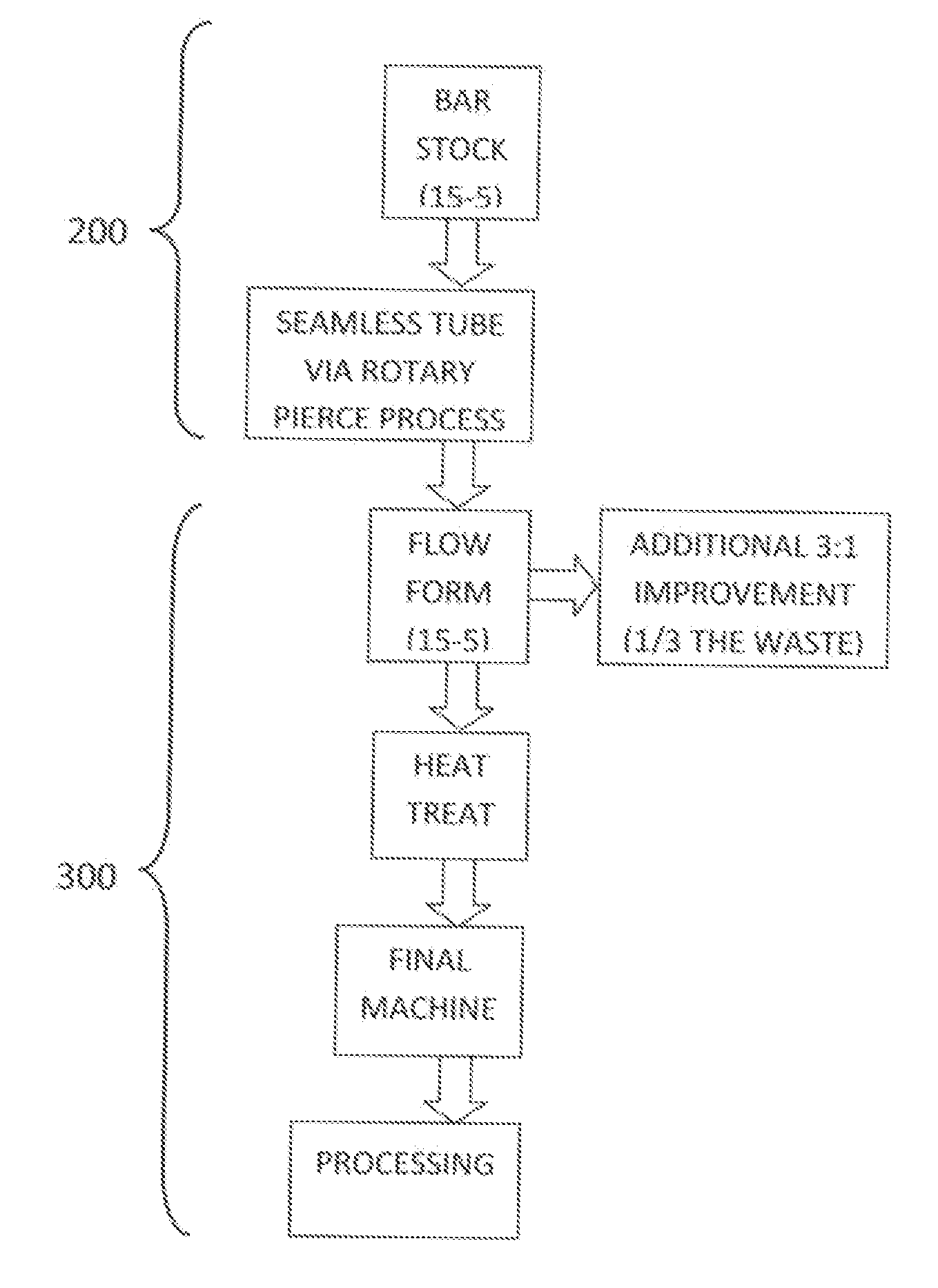
[0033]A description of preferred embodiments of the invention follows. While this invention has been particularly shown and described with references to preferred embodiments thereof, it will be understood by those skilled in the art that various changes in form and details may be made therein without departing from the scope of the invention encompassed by the appended claims.

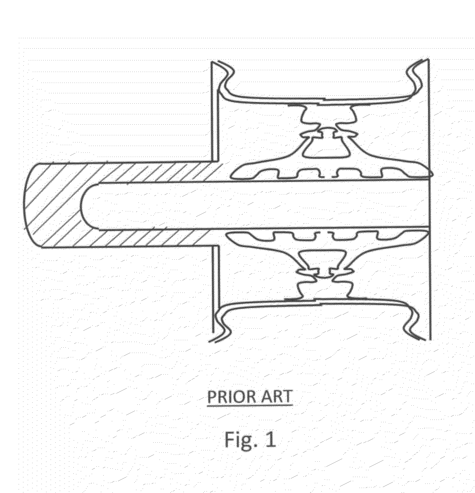
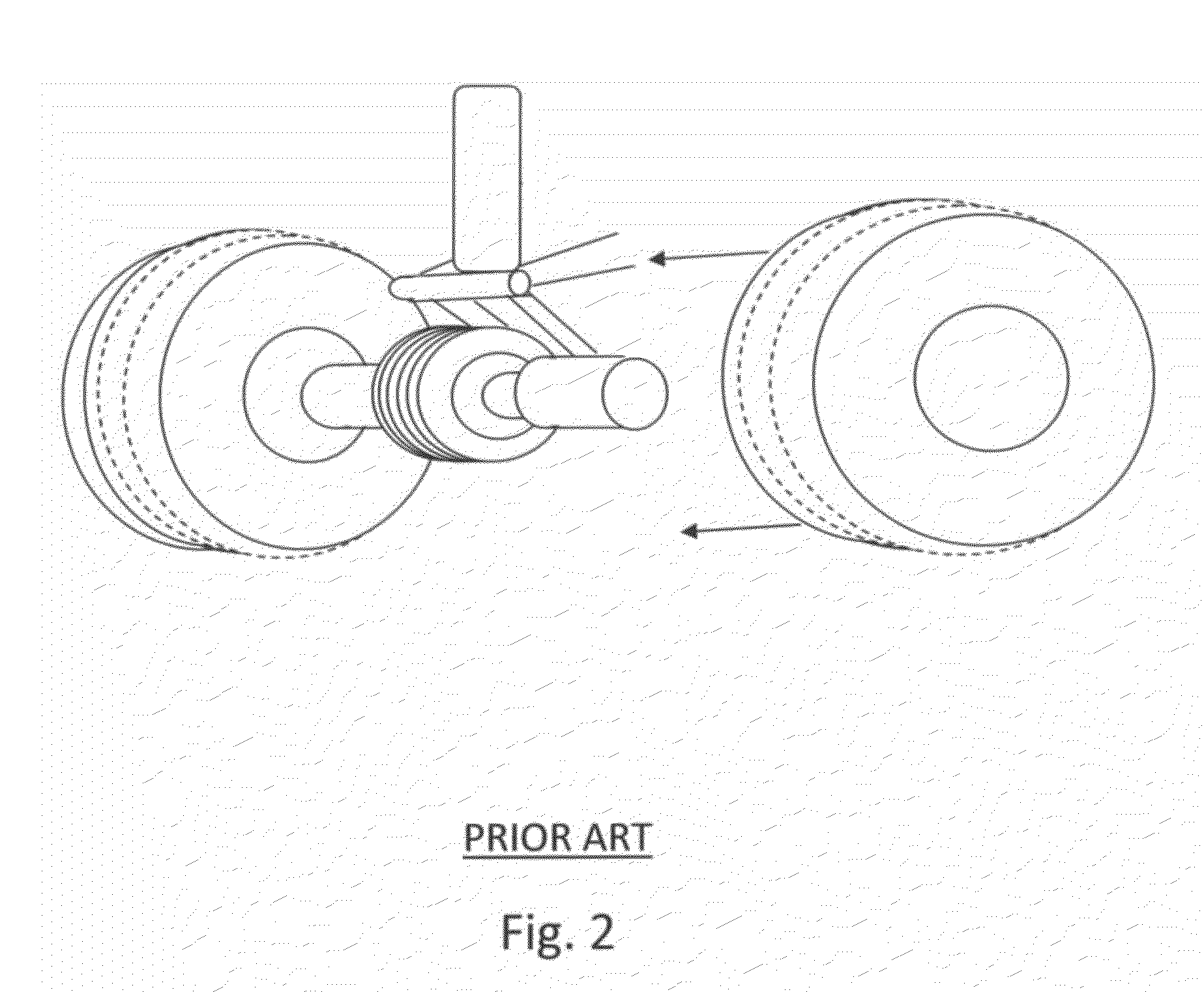
[0034]Flowforming is an advanced cold-forming process for the manufacture of hollow components. Flowforming allows for the production of dimensionally precise and rotationally symmetrical components and is typically performed by compressing the outside diameter of a cylindrical component or preform over an inner rotating mandrel using a combination of axial and radial forces from one or more rollers. The metal is compressed and plasticized above its yield strength and made to flow in the axial direction onto a mandrel. The workpiece being formed, the rollers, and / or the mandrel can rotate. Two examples of flow...


PUM

PropertyMeasurementUnit
Fractionaaaaaaaaaa
Fractionaaaaaaaaaa
Fractionaaaaaaaaaa

Abstract

A system and method for the manufacture of aircraft landing gear axle equipment is provided of two primary steps: hot pierce and tube solid billet stock; and flow form process. The hot pierce and tube process converts a standard solid round billet by heating it well beyond its annealing temperature. The billet is then pierced with a lance and hot rolled into a seamless tube. The tube is then precision flow formed as an incremental metal forming technique in which a tube of metal is formed over a mandrel by a multiple rollers using tremendous pressure. The rollers deform the work piece, forcing it against the mandrel, simultaneously lengthening the part axially and radially thinning the cross-sectional wall of the workpiece.

Description

RELATED APPLICATIONS[0001]The present application claims the benefit of U.S. Provisional Application 61 / 356,190, filed on Jun. 18, 2010 and incorporated by reference as if fully rewritten herein.BACKGROUND OF THE INVENTION[0002]1. Technical Field of the Invention[0003]The present invention relates generally to the manufacture of aircraft landing gear axle equipment and, in particular, to the application of room temperature rotary metal forming technology in the production of aircraft landing gear axle equipment.[0004]2. Description of the Background Art[0005]Axle sleeves, wheel sleeves and brake sleeves are commonly utilized in aircraft landing and brake systems. These sleeves protect the aircraft axle by providing protection from foreign object damage during flight operations. By way of example, as shown in FIG. 1 and FIG. 2, the axle sleeve on a Airbus™ A330 is shown according to the PRIOR ART, forming a thin, protective, consumable member mounted between the axle and wheel bearin...

Claims


Application Information

Patent Timeline
IPC IPC(8): F16L55/00B23P11/00C22F1/00B23B3/00B60B37/00C21D9/08
CPCB21J5/063B21J5/10B60B35/04B60B35/08C21D8/10Y10T29/49826C21D9/08C21D9/28C22F1/04C22F1/183Y10T82/10C21D8/105B21D22/16
Inventor YORI, III, RICHARD B.LIOI, PAUL
Owner THE NAT MASCH CO
Why Eureka
Try Eureka