Roll mold, method for fabricating the same and method for fabricating thin film pattern using the same

a technology of rolling molds and rolls, applied in the direction of dough shaping, manufacturing tools, applications, etc., can solve the problems of increasing fabrication costs, complicated masking process, and complicating the overall manufacturing process, so as to prevent dimensional variation of rolling molds and simplify the overall manufacturing process.

Active Publication Date: 2012-02-16
LG DISPLAY CO LTD
View PDF5 Cites 7 Cited by
  • Summary
  • Abstract
  • Description
  • Claims
  • Application Information

AI Technical Summary

Benefits of technology

[0010]It is one object of the present invention to provide a roll mold, a method for fabricating the same and a method for fabricating a thin film pattern using the same, to prevent dimensional variation of the roll mold and simplify the overall manufacturing process.

Problems solved by technology

However, the mask process is complicated, thus disadvantageously increasing fabrication costs.
The roll mold 10 requires two etching processes, thus complicating the overall manufacturing process.
The diameter of the base roller 14 is decreased through two etching processes, thus disadvantageously causing variation in the final size of the roll mold 10 and deformation thereof.

Method used


Image

  • Roll mold, method for fabricating the same and method for fabricating thin film pattern using the same
  • Roll mold, method for fabricating the same and method for fabricating thin film pattern using the same
  • Roll mold, method for fabricating the same and method for fabricating thin film pattern using the same

Examples


first embodiment

[0043]FIGS. 3A to 3E are sectional views illustrating a method for fabricating the roll mold illustrated in FIG. 2 according to a

[0044]As shown in FIG. 3A, a master pattern layer 112 having a groove pattern 112a and a protrusion pattern 112b is formed on a master substrate 110 having a flat surface. The master pattern layer 112 is formed by applying an organic material, which can be stripped, such as photoresist, and patterning the material through photolithography, holographic lithography, laser processing, electron beam processing, focused ion beam processing or the like. Meanwhile, the master pattern layer 112 and the master substrate 110 are separately formed, or a master pattern whose surface has a groove pattern and a protrusion pattern may be formed by patterning the master substrate 110.

[0045]The master pattern layer 112 may be surface-treated with a self-assembled monolayer (SAM) to facilitate release (detachment) of the master pattern layer 112 from the mold surface layer ...

second embodiment

[0058]FIGS. 6A to 6C are views illustrating a method for patterning a thin film via a printing method employing the roll mold of the present invention according to a

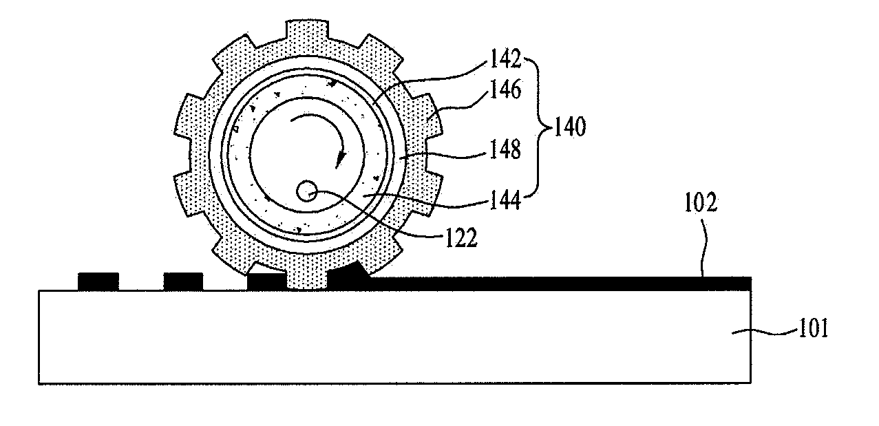
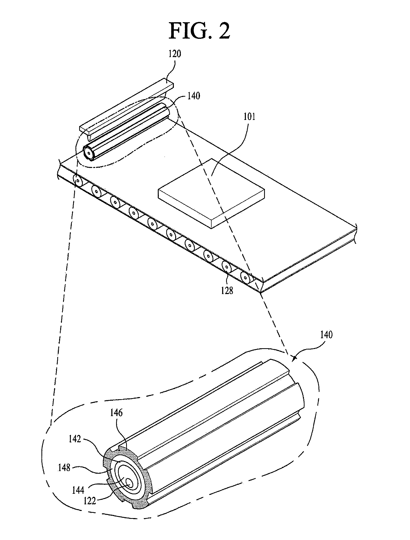
[0059]As shown in FIG. 6A, a roll mold 140 including a base roller 144, an adhesive resin layer 142, a buffer layer 148 and a master pattern layer 146 is provided. The printing liquid 102 supplied from the printing liquid supplier 120 fills the groove of the roll mold 140.

[0060]Next, as shown in FIG. 6B, the roll mold 140 filled with the printing liquid 102 is rolled over the substrate 101. Accordingly, the printing liquid 102 is cured through a curing apparatus, such as a UV lamp, provided in the base roller 144 of the roll mold 140, or a curing apparatus provided on the rear surface of the substrate 101. Accordingly, the printing liquid 102 is transcribed, dried and cured on the substrate 101 and is thus formed into a thin film pattern, as shown in FIG. 6C.

third embodiment

[0061]FIGS. 7A to 7D are views illustrating a method for patterning a thin film via a printing method employing the roll mold of the present invention according to a

[0062]As shown in FIG. 7A, a roll mold 140 including a base roller 144, an adhesive resin layer 142, a buffer layer 148 and a master pattern layer 146 is provided. The printing liquid 102 supplied by the printing liquid supplier 120 fills the groove of the roll mold 140.

[0063]Next, as shown in FIG. 7B, the printing liquid 102 is transcribed to a transcription roller 106, which rotates, and, at the same time, is engaged in the roll mold 140. The transcription roller 106 provided with the printing liquid 102 is rolled over the substrate 101, as shown in FIG. 7C. Accordingly, the printing liquid 102 is transcribed, dried and cured on the substrate 101 and is thus formed into a thin film pattern, as shown in FIG. 7D.

[0064]As such, the thin film pattern 104 shown in FIGS. 5C, 6C and 7D may be used to form thin or thick films ...


PUM

PropertyMeasurementUnit
hydrophobicaaaaaaaaaa
flexibleaaaaaaaaaa
sizeaaaaaaaaaa

Abstract

Discussed are a roll mold, a method for fabricating the same and a method for fabricating a thin film pattern using the same, to prevent dimensional variation of the mold and simplify the overall process. The method for fabricating a roll mold includes providing a substrate provided with a master pattern layer, sequentially forming a mold surface layer and a solid suffer layer on the substrate provided with the master pattern layer to provide a flat panel mold, forming an adhesive resin layer on the base roller aligned on the flat panel mold, and rolling the base roller provided with the adhesive resin layer over the flat panel mold to adhere the flat panel mold to the base roller through the adhesive resin layer.

Description

[0001]This application claims the priority benefit of Korean Patent Application No. 10-2010-0078308, filed on Aug. 13, 2010, which is hereby incorporated by reference as if fully set forth herein.BACKGROUND OF THE INVENTION[0002]1. Field of the Invention[0003]The present invention relates to a roll mold, a method for fabricating the same and a method for fabricating a thin film pattern using the same.[0004]2. Discussion of the Related Art[0005]A variety of flat panel display devices to reduce weight and volume of the problems of cathode ray tubes have been introduced. Examples of flat panel display devices include liquid crystal display devices, field emission display devices, plasma display panel devices and electroluminescent (EL) display devices.[0006]Such a flat panel display device includes a plurality of thin films formed by a mask process including a series of deposition (coating), exposure to light, developing and etching processes. However, the mask process is complicated, ...

Claims


Application Information

Patent Timeline
Patent Type & Authority Applications(United States)
IPC IPC(8): B29C59/04B29C63/10B65H81/06
CPCB29C33/40B29C33/424B29C2035/0827B29C33/3857B29C2033/385B05D3/12B05D3/06B05D5/00H01L21/0274
Inventor LEE, NAM-SEOKKIM, CHUL-HOLEE, SHIN-BOK
Owner LG DISPLAY CO LTD
Why Eureka
Try Eureka