Stent to be used in tubular organ in vivo

a tubular organ and stent technology, applied in the field of stents, can solve the problems of high mortality rate, complex tubular structure, and inability to adapt to the structure of complex structures, and achieve excellent mechanical flexibility and design freedom

Inactive Publication Date: 2012-02-16
YASUHIRO SHOBAYASHI
View PDF2 Cites 16 Cited by
  • Summary
  • Abstract
  • Description
  • Claims
  • Application Information

AI Technical Summary

Benefits of technology

[0007]An object of the present invention is to provide a stent to be inserted to be placed for use in the inner cavity of an in vivo tubular organ that has a degree of freedom in design and excellent mechanical flexibility.
[0008]The present inventors have intensively examined the structures of stents having closed cell structures (and thus having good flexibility) that can be safely used for in vivo organs having cyclic structures without allowing some wires (struts) to protrude outside the stent. The present inventors have conducted structural analysis for stents having closed cell structures and various mesh patterns using a finite element method. In addition, the present inventors have actually produced such stents and verified the validity of the structural analysis thereof.
[0009]As a result, the present inventors have discovered a mesh pattern that can allow a degree of freedom in stent design and imparts flexibility to stents, and thus they have completed the present invention.
[0010]Furthermore, the present inventors have discovered the following: a tubular stent having the above mesh pattern can be braided with wires, so that the prevention of blood flow into a mass such as an aneurysm or varix while retaining the flexibility of the stent and the prevention of the rupture of such a mass can be expected, for example.

Problems solved by technology

Most in vivo tubular structures are complex such as in the cases of bending structures.
Hence, the insertion of a stent into a site having such a complicated structure requires mechanical flexibility.
A brain aneurysm rupture causes the onset of cerebral hemorrhages such as subarachnoid hemorrhages that result in high mortality rates.
Among in vivo organs having tubular structures, the cerebrovascular system has a particularly complicated structure, in which many sites characterized by a large degree of curvature are present.
However, concerns have been raised that in a stent having an open cell structure, some wires (struts) may protrude outside the stent when it is bent, so as to injure in vivo tubular tissue such as the tissue of a blood vessel into which the stent has been inserted to be placed.
However, stents having closed cell structures may have poor flexibility because of their structures.
Hence, there has been doubt about the usefulness of such a stent for the cerebrovascular system, which requires a particularly flexible stent.
However, the relationship between a mesh pattern having a closed cell structure and flexibility has not yet been analyzed.

Method used


Image

  • Stent to be used in tubular organ in vivo
  • Stent to be used in tubular organ in vivo
  • Stent to be used in tubular organ in vivo

Examples


example 1

Preparation of and Property Test for Tubular Stent

3DCAD Stent Model

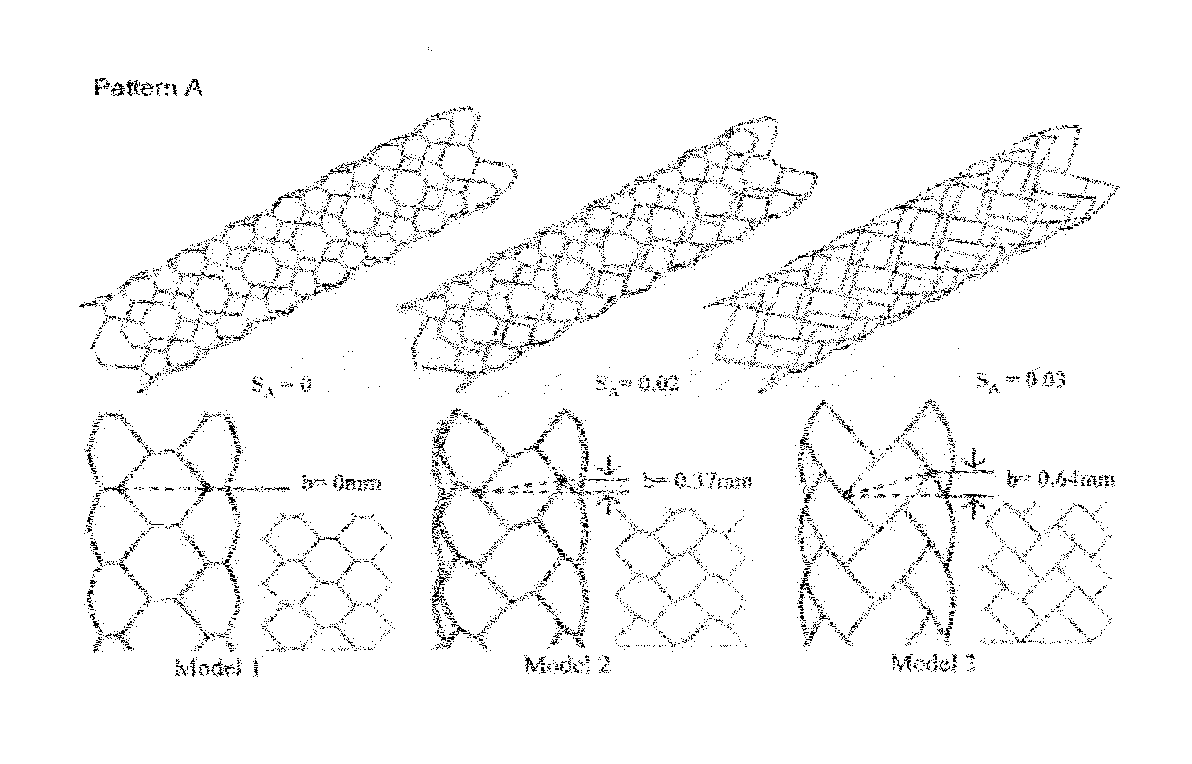
[0124]In this example, a stent model having a closed-cell structure was designed on the basis of Pythagorean tessellation theory. This theory was employed because the mesh pattern of the stent having the closed-cell structure is composed so that it is filled with cells all having the same shape. According to the Pythagorean tessellation theory, the only geometrical shapes that can planarly fill a plane are quadrangles and hexagons (to be precise, triangles are also included).

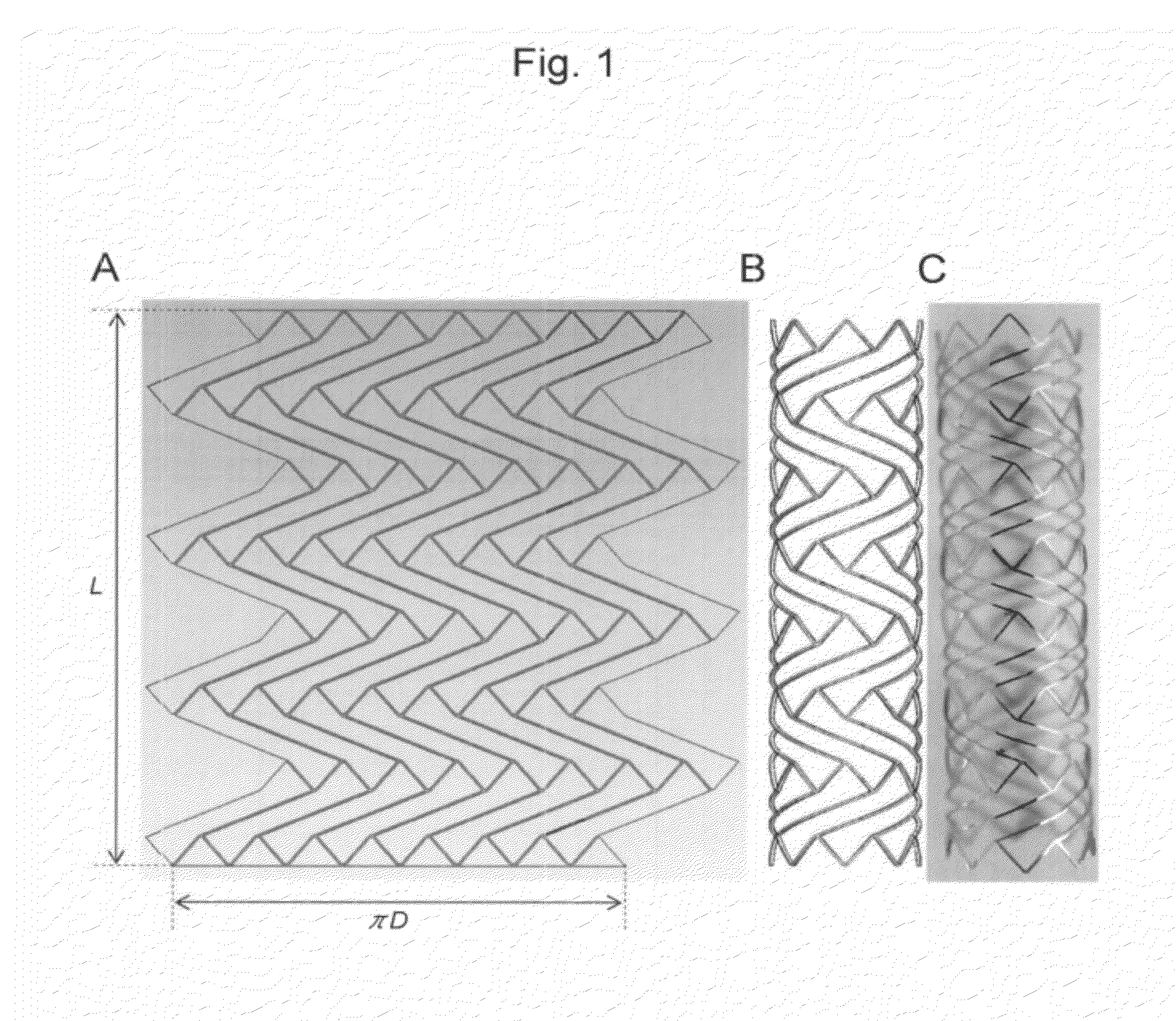
[0125]A real-shape 3DCAD stent model was created using Solid Edge (SIEMENS PLM Software). Thereafter, the model was imported in IGES format into Pro / ENGINEER (Parametric Technology Corporation) and Rhinoceros (Robert McNeel & Associates) so that the surface model could be modified. A finite element model was then created with Marc. Mentat finite element software (MSC Software).

[0126]Mesh patterns with 3 types of closed cell structure were devised...

example 2

Preparation of and Property Test for Hybrid Stent Braided with Wires

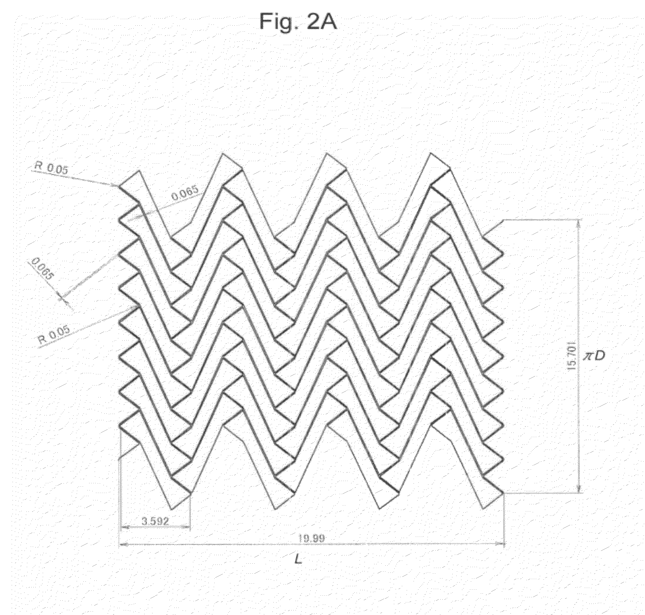
[0154]The tubular stent model 6 in Example 1 was braided with wires. The stent was composed of an Ni—Ti tube and the diameter, length, thickness, and wire width of the tube were 5.0 mm, 20 mm, 0.115 mm, and 0.065 mm, respectively. These were 7 cells in the longitudinal direction and 8 cells in the circumferential direction. Wire made of a nickel titanium alloy having a diameter of 39 μm and a length of 30 cm was used. As shown in FIG. 29, a wire was inserted into a cell (which is located near the center of the stent in the longitudinal direction) from the outside to the inside of the stent and then the wire was guided to move outside from the inside of the stent via the adjacent cell so that it crossed the strut forming the cell. Through repetition of this procedure, the stent was braided with wires so that the wires crossed the stent struts alternately. At such time, braiding was performed so that wires obliquely e...


PUM


Abstract

Provided is a stent to be inserted into an in vivo organ having a tubular structure that allows a degree of freedom in design and excellent mechanical flexibility. A cylinder-shaped stent is inserted to be placed and used in the inner cavity of an in vivo tubular organ, wherein: the wall of the stent has a planar mesh pattern filled with a plurality of closed cells being adjacent to each other and having congruent shapes; the closed cells have point-symmetric parallel hexagonal shapes; all closed cells circumferentially adjacent to each other are congruent and similar in shape; two closed cells adjacent to each other sharing different sides form a substantially V-shaped member; and the vertex of each folded part in the substantially V-shaped member points to the circumferential direction.

Description

TECHNICAL FIELD[0001]The present invention relates to a stent inserted to be placed and used in the inner cavity of an in vivo tubular organ.BACKGROUND OF THE INVENTION[0002]Cylindrical stents to be inserted to be placed for use in in vivo organs having tubular structures (e.g., blood vessels, esophagus, and trachea) are used in order to expand or maintain tubular structures for treatment of aneurysm, thrombosis, or the like.[0003]Most in vivo tubular structures are complex such as in the cases of bending structures. Hence, the insertion of a stent into a site having such a complicated structure requires mechanical flexibility.[0004]For example, a brain aneurysm is a type of aneurysmal vascular lesion that is generated on the arterial wall of a cerebral blood vessel. A brain aneurysm rupture causes the onset of cerebral hemorrhages such as subarachnoid hemorrhages that result in high mortality rates. Stents are also used in intravascular operations for such brain aneurysms. Among in...

Claims


Application Information

Patent Timeline
Patent Type & Authority Applications(United States)
IPC IPC(8): A61F2/82A61F2/04A61F2/91A61F2/915
CPCA61F2/91A61F2002/91575A61F2/915
Inventor SHOBAYASHI, YASUHIROTANISHITA, KAZUOTATESHIMA, SATOSHI
Owner YASUHIRO SHOBAYASHI
Why Eureka
Try Eureka