
System and method of monitoring vibration of a blasting model test for a jointed rock mass

a technology of vibration monitoring and model, applied in the field of deep rock mechanics, can solve the problems of inability to capture and analyze crack evolution process and cracking mechanism of jointed rock mass under blasting load in real time, and the test means used in this test cannot monitor both the impact of blasting stress waves on the stability of existing jointed-surrounding-rock tunnels and the impact of blasting stress waves on the stability of jointed rock masses

Pending Publication Date: 2022-08-04
ANHUI UNIV OF SCI & TECH
View PDF0 Cites 3 Cited by
  • Summary
  • Abstract
  • Description
  • Claims
  • Application Information

AI Technical Summary

Benefits of technology

The present invention provides an improved system and method for monitoring vibrations caused by blasting in a jointed rock mass. The system includes a transparent jointed rock mass model with high-speed photography and monitoring capabilities, as well as piezoelectric pressure sensors that are effective in preventing water interference and measuring large deformations. The method also includes steps for preparing and handling the model, as well as analyzing the impact of blasting on stability of existing tunnels. The invention enables the study of joint inclination angle, different blasting modes, and dynamic crack-evolution process in real-time, providing reliable and truer test data.

Problems solved by technology

Blasting vibration is an important factor that induces dynamic instability of deep-mine tunnels.
However, there are few researches on the mechanism of action that the blasting vibration induces the dynamic instability of the surrounding rocks of the deep-mine tunnels.
However, this device and the method cannot capture and analyze a crack evolution process and a cracking mechanism of the jointed rock mass under blasting load in real time.
However, test means used in this test can neither monitor both the impact of the blasting stress waves on the stability of existing jointed-surrounding-rock tunnels and the impact of the blasting stress waves on the stability of the jointed rock masses, nor capture and analyze a crack evolution mechanism of the jointed surrounding rock or a crack evolution mechanism of jointed-surrounding-rock tunnels under the blasting load.
However, this method uses a foil resistance strain gauge which cannot monitor and record large deformations of the surrounding rocks under the blasting load.
Furthermore, this method is easily affected by the electromagnetic interference generated by the blasting load.
So, test errors are generated, and the method cannot analyze the influence of the joint inclination angle on the propagation and attenuation laws of the blasting stress waves in the jointed rock masses.
1) The crack evolution process and the cracking mechanism of the jointed rock mass under the blasting load are not captured and analyzed in real time.
2) The impact of the blasting stress waves on the stability of the existing jointed-surrounding-rock tunnels and the impact of the blasting stress waves on the stability of the jointed rock masses are not monitored.
3) The traditional strain measurement technology cannot monitor and record the large deformations of the surrounding rock under the blasting load, and is easily affected by the electromagnetic interference, thereby resulting in test errors.
4) The omnibearing monitoring and recording for the impact of blasting vibration on the existing tunnels cannot be performed, and the influence of different millisecond blasting modes on the existing tunnels cannot be analyzed.

Method used


Image

  • System and method of monitoring vibration of a blasting model test for a jointed rock mass
  • System and method of monitoring vibration of a blasting model test for a jointed rock mass
  • System and method of monitoring vibration of a blasting model test for a jointed rock mass

Examples


first embodiment

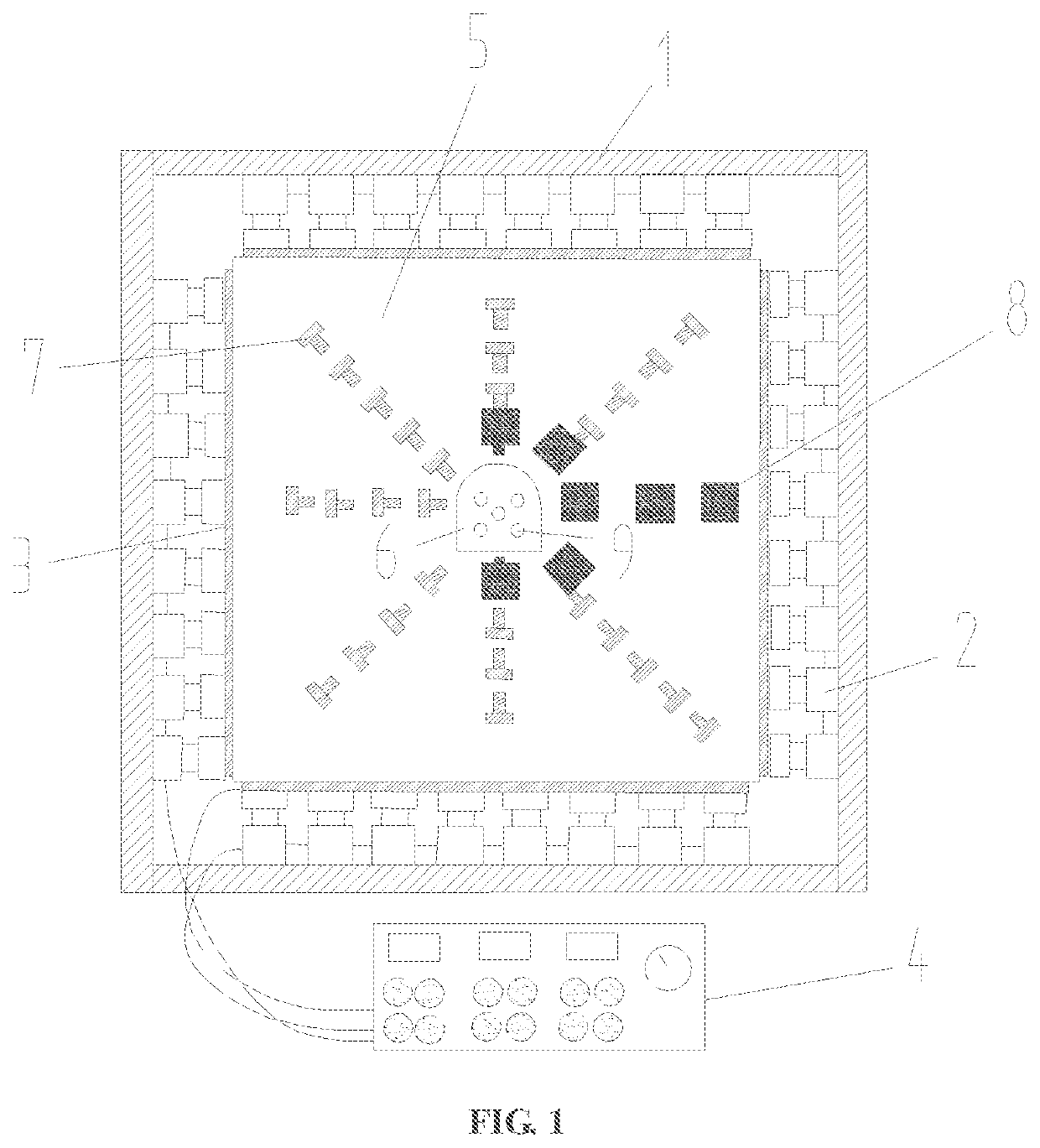
[0046]In a first embodiment, an improved system of monitoring vibration of a blasting model test for a jointed rock mass includes: a loading subsystem for three-way load, a model-surface blasting-vibration acquisition subsystem, and a model-interior dynamic stress-strain acquisition subsystem. The loading subsystem for three-way load includes a reaction frame 1, a hydraulic jack 2, a force transfer plate 3, and a three-way pressure control console 4. The model-surface blasting-vibration acquisition subsystem includes a three-dimensional strain rosette 7, an ultra-dynamic resistance strain gauge, a dynamic test analyzer, and a blasting vibration monitor 8. The model-interior dynamic stress-strain acquisition subsystem includes fiber grating strain sensors 13, and PVDF (Polyvinylidene fluoride) piezoelectric pressure sensors 14.

[0047]The three-dimensional strain rosette 7 and the blasting vibration monitor 8 are both arranged on a non-loading surface of a jointed rock mass model 5. Th...

second embodiment

[0057]In a second embodiment, the method for monitoring blasting vibration of a jointed rock mass includes the following steps one to eight.

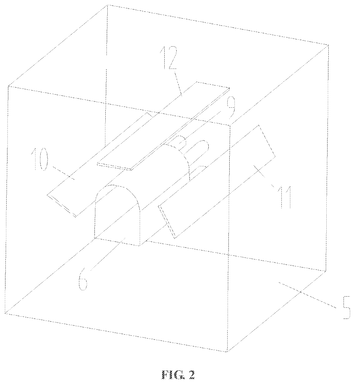
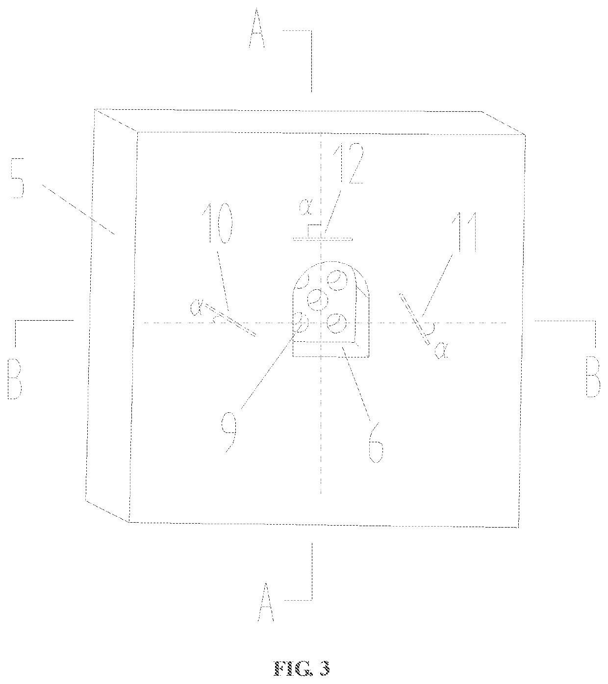
[0058]In step one, determination of relevant dimensions of a jointed rock mass model: an existing tunnel of the jointed rock mass model is enabled to be a circular cavity commonly used in deep underground engineering; an excavation diameter Φ1 and a tunneling depth d1 of the existing tunnel 6 are determined according to a similar theory and a size of the jointed rock mass model; a diameter Φ2 and a depth d2 of each of blasting holes 9 are determined; sheet mica with different angles is fixed in a mold according to test needs; and a first layer of transparent rock-like material is poured, where a pouring thickness is equal to a difference value among a thickness d of the mold, the tunneling depth d1 and the depth d2 of each of the blasting holes.

[0059]In step two, reservation of the blasting holes: seamless steel pipes are preset at a center of a...


PUM


Abstract

An improved system of monitoring vibration of a blasting model test for a jointed rock mass and a method are provided. The system includes: a loading subsystem for three-way load, a model-surface blasting-vibration acquisition subsystem, and a model-interior dynamic stress-strain acquisition subsystem. The system and the method are provided, and a blasting model for a transparent jointed rock mass and a monitoring method that are obtained can analyze the influence of a joint inclination angle on propagation and attenuation laws of blasting stress waves in the jointed rock mass, and can analyze the influence of different millisecond blasting modes on the stability of an existing tunnel in the jointed rock mass, and can capture a real-time dynamic evolution process of cracks. The stress and strain measurement technologies used can perform omnibearing monitoring and recording for large deformations of surrounding rock under blasting load, and can resist the electromagnetic interference.

Description

CROSS REFERENCE TO RELATED APPLICATION[0001]This patent application claims the benefit and priority of Chinese Patent Application No. 202011249459.7 filed on Nov. 10, 2020, the disclosure of which is incorporated by reference herein in its entirety as part of the present application.TECHNICAL FIELD[0002]The present disclosure belongs to the field of blasting theory and technology, and deep rock mechanics, and particularly relates to an improved system and a method of monitoring vibration of a blasting model test for a jointed rock mass.BACKGROUND ART[0003]Blasting vibration is an important factor that induces dynamic instability of deep-mine tunnels. The researches on the dynamic instability of surrounding rocks of the deep-mine tunnels under the blasting vibration mainly focus on following aspects: the deformation of the surrounding rocks of the tunnels under the blasting vibration, the deterioration of the surrounding rocks of the tunnels during propagation of blasting vibration w...

Claims


Application Information

Patent Timeline
IPC IPC(8): G01N3/313G01N3/06G01N33/24G01V99/00E21D9/00
CPCG01N3/313G01N3/066G01N3/068G01N33/24G01V99/005G01N2203/0641G01N2203/001G01N2203/003G01N2203/0075G01N2203/0623E21D9/003G01H11/08G01N2203/0066G01N2203/0647E21D9/00G01H1/00G01H9/004G01V1/01G01V20/00
Inventor MA, QINYONGSU, QINGQINGYUAN, PU
Owner ANHUI UNIV OF SCI & TECH
Learn More